11-3
11-1 Access Window Overview
ACCESS WINDOW
- SV Series User’s Manual -
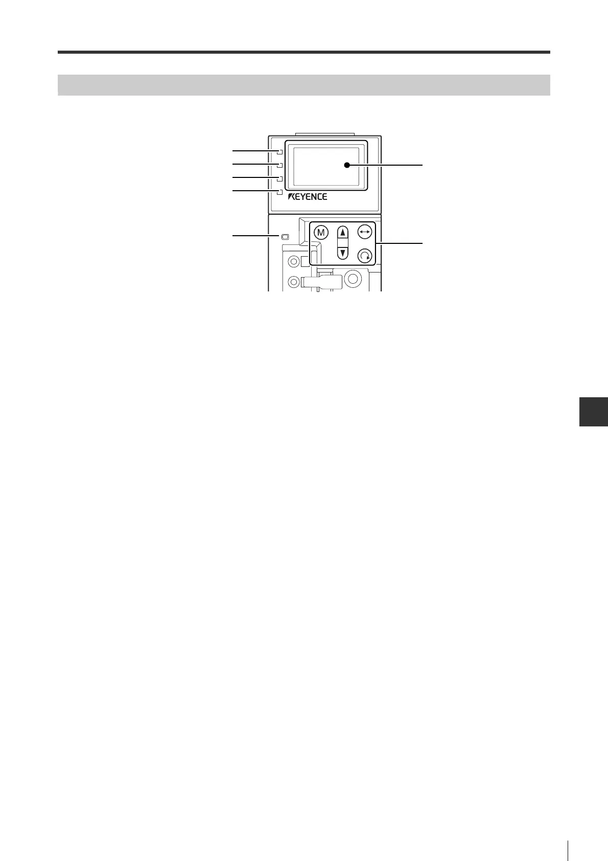
Components in Access Window
The name and function of each component in the Access Window:
1 LCD
For displaying operating status, set values, and alarms. The screen turns green when the unit works properly and
turns red in case of error.
2 Keys
For switching different modes and changing set values.
3 Servo ON LED
When servo ON, the lamp is lit.
4 Command Input LED
The LED is lit in one of the following cases:
Position control : When servo ON and command pulse is input (MECHATROLINK-II type)
When command pulse is input (pulse/analog input type)
Speed control :
Servo ON and the speed command input is higher than "Zero speed detection range" (for VEL_15)
Torque control : Servo ON and the command input is higher than 10% of rated torque
5 Warning LED
The LED is lit when an warning occurs.
6 MECHATROLINK-II LED
The LED is lit when MECHATROLINK-II communication is undertaken.
* This is not available in the pulse/analog input type.
7 CHARGE LED
The LED is lit when the power of main circuit is ON.
SV ON
CMD
WARN
COM
 Loading...