4-10
SIGNALS AND WIRING
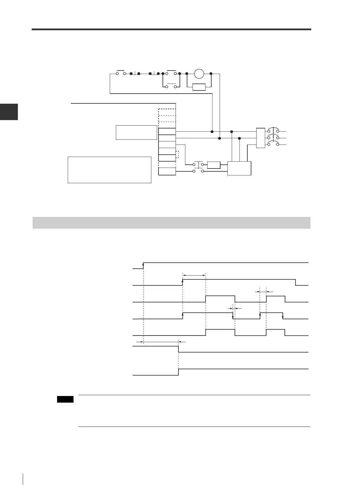
4-3 Wiring the Power Supply of Main/Control Circuit
- SV Series User’s Manual -
Wiring example is as follows.
* Short the B2 and B3 terminals when using SV-0752/1002/1502/2002/3002/5002.
Do not short the B2 and B3 terminals when using SV-0052/0102/0202/0402.
Power ON Sequence
"Alarm" signal can be output up to 5 seconds when control circuit is powered on.
After control circuit power is ON, at least 5 seconds of idle time must be left before inputting control signal.
Main circuit power and control circuit power should be connected simultaneously, or first control circuit
power and then main circuit power.
When turning off the power turn off the main circuit first, then the control circuit.
NFB : No fuse breaker
MC : Magnetic contactor
FIL : Noise filter
SA : Absorber (surge killer)
RA : Alarm output relay
Emergency
stop
Main circuit
ON
Main
circuit OFF
RA
Main circuit/control circuit
power supply connector
Servo amplifier (SV-
ƶƶƶƶ
2)
MC
SA
L1C
L2C
MC
B1/
-
2
ƻ
○
+
NFB
FIL
R
S
T
AC/DC
MC
+
-
Fuse
B2
B3
※
Power supply of control circuit
Power supply of main circuit
Control signal input
acceptance
ALARM
Servo ON signal input
Servo motor excitation
unavailable
available
OFF
ON
OFF
ON
OFF
ON
OFF
ON
OFF
ON (Warning status)
OFF
ON
Up to 5.0s
> 276ms
> 6ms
> 36ms
Ready to operate (RDY)
 Loading...