4-38
SIGNALS AND WIRING
- SV Series User’s Manual -
4-6 Wiring Regenerative Resistor
This section describes the specification and connection of regenerative resistors.
Regenerative Resistors Specifications
The specifications of built-in regenerative resistor (750W to 5kW) and external regenerative resistor are as follows.
■ Built-in regenerative resistor (only for 750W)
■ External regenerative resistors
How to Connect Regenerative Resistors
Connection of regenerative resistor is described as follows. For how to select regenerative resistor, see "5-4
Regenerative Resistor Setting", page 5-23.
Wiring of regenerative resistors must be correct. Otherwise this may lead to machine damage and fire.
Regenerative resistors can be connected as follows.
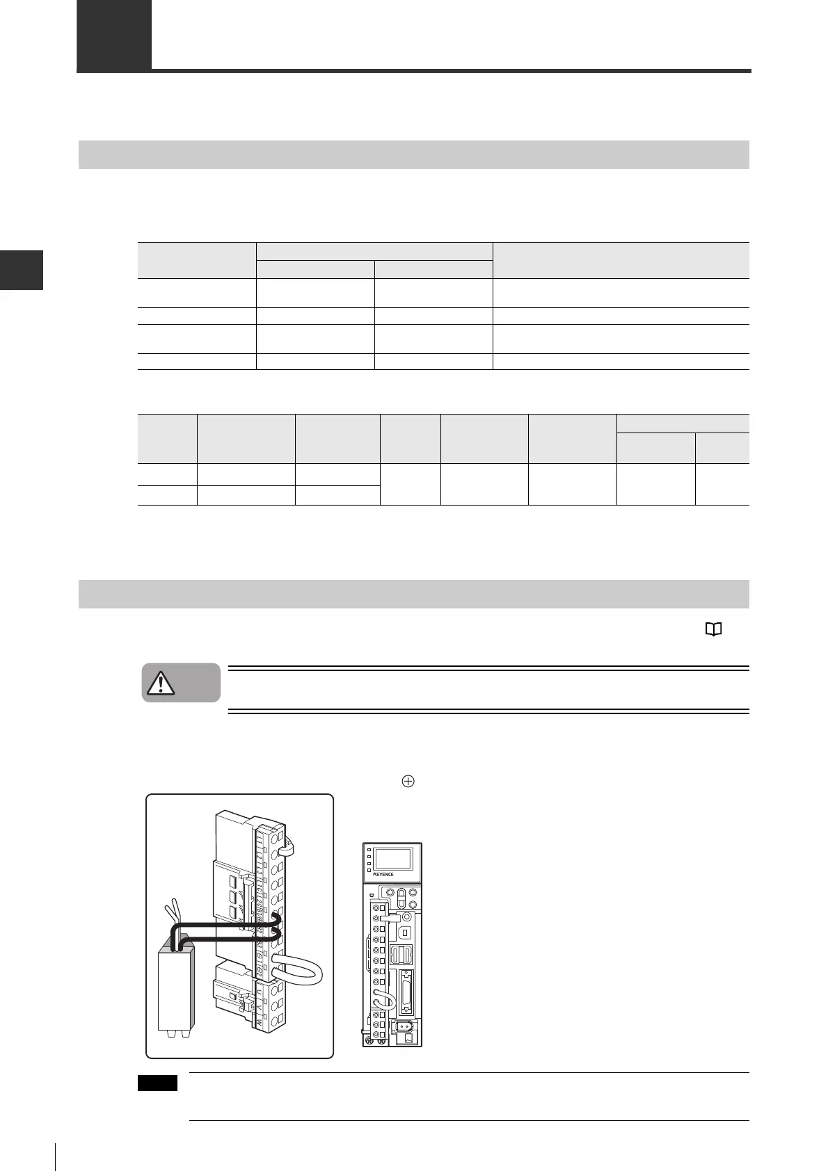
■
Connecting regenerative resistor with SV-005
, SV-010
, SV-020
or SV-040
The regenerative resistor can be connected to B1/ and B2 terminals independent on the polarity.
For 100V type servo amplifier, terminal assignment is different. Do not confuse the terminals to be
connected.
Model of servo
amplifier
Built-in regenerative resistors
Regenerative power[W]
Resistance value[
Ω
]
Capacity[W]
SV-0752
SV-1002
50 40 8
SV-150220 50 10
SV-2002
SV-3002
12 80 16
SV-5002 8 180 36
Model
Applicable
capacity of
servo amplifier
Resistance
value[Ω]
Rated
capacity
[W]
Ambient
temperature
[°C]
Storage
temperature [
°
C]
Thermostat
Max. contact
rating
Contact
mode
OP-84399 50W to 1kW 50±5%
220
*1
*1 Rated capacity refers to the value at environment temperature of 70°C. However, for natural air cooling please
use the capacity of up to 20%.
-
30 to 80
-
40 to 100
AC115V/22A
AC277V/8A
DC16V/20A
N.C.
OP-87073 1.5kW
*2
*2 2kW to 5kW can also be used depending on operational conditions.
20±5%
Danger
External regenerative resistors
 Loading...