2-6
2-2 Names and Functions of Parts
- SV Series User’s Manual -
CONFIGURATION & SPECIFICATIONS
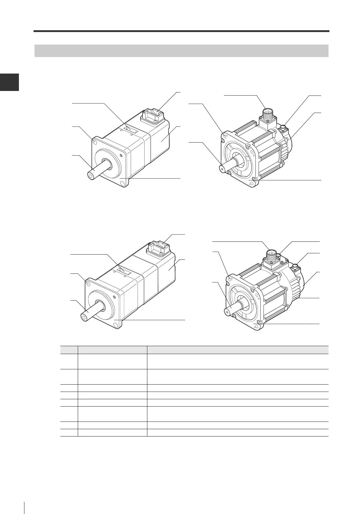
Name and Function of Each Part of the Servo Motor
■ Standard motor
■ Electromagnetic brake motor
*1 For 50W to 750W electromagnetic brake motors, the electromagnetic brake cable connector and the motor
power cable connector are integrated.
• 50W to 750W • 1kW to 5kW
(5)
(1)
(2)
(3)
(8)
(4)
(4)
(5)
(8)
(1)
(2)
(3)
(1)
(2)
(3)
(8)
(5)
(4)
(4)
(5)
(6)
(8)
(7)
(1)
(2)
(3)
• 50W to 750W • 1kW to 5kW
No. Name Function
(1)
Connector for motor power
cable
*1
To connect motor power cables. protective sealing strips(covers for 1kW to 5kW
servo motors) are attached at ex-factory.
(2) Mounting hole
To mount the servo motor. (2 holes for 50W and 100W servo motors, 4 holes for
200W to 5kW servo motors)
(3) Output axis Rotating axis of the servo motor. Including straight axis and axis with keyway.
(4) Encoder cable connector
To Connect encoder cables. Attached with a cover at ex-factory.
(5) Encoder Built-in encoder.
(6)
Electromagnetic brake cable
connector
*1
To connect electromagnetic brake cables. Attached with a cover at ex-factory.
(7) Electromagnetic brake Built-in electromagnetic brake.
(8) Flange The surface on the machine for mounting a servo motor.
 Loading...