4-8
SIGNALS AND WIRING
4-3 Wiring the Power Supply of Main/Control Circuit
- SV Series User’s Manual -
Wiring the Power Supply of Main/Control Circuit
Wiring the power supply of main/control circuit is described as follows.
For internal circuit of the servo amplifier, see "A-2 Internal Block Diagram", page A-18.
■ 3-phase AC200V (when SV-2 is used)
For wiring example, see "4-2 Standard Wiring Diagram", page 4-3.
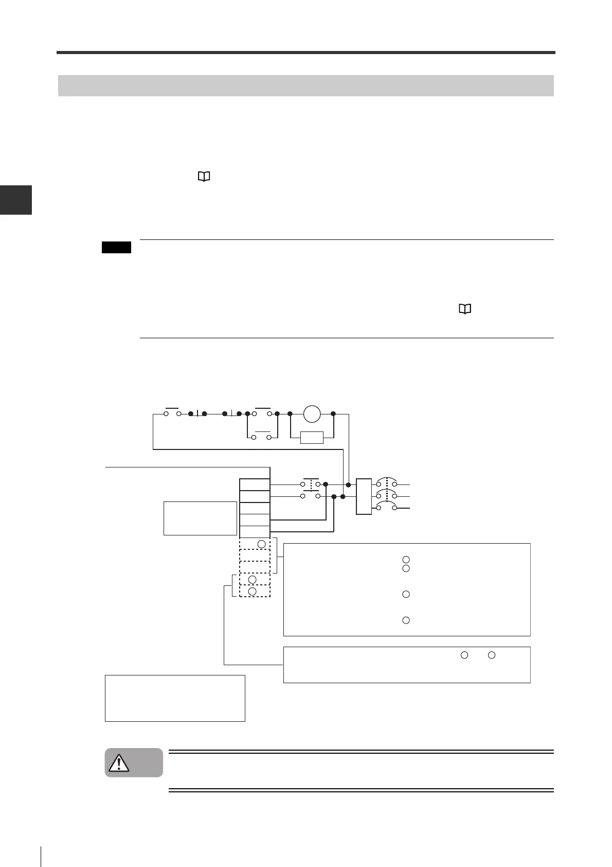
■ 1-phase AC200V (when SV-2 is used)
To wire L1/L2 when 1-phase AC200V is used.
• Do not connect with L3.
Be sure to change "*3PH/1PH power supply" (OTH_11) to "single phase". "Main circuit open
phase" alarm (F10) will occurwhen "three phase" is set.
• When 1-phase AC200V is used, torque-speed characteristics of servo motor may not be able to
meet the characteristics of 3-phase power input. For details, See "2-4 Servo Motor
Specifications", page 2-12.
Wiring example is as follows.
If you wiring the terminals marked with "Not used", the servo amplifier may be damaged.
NFB : No fuse breaker
MC : Magnetic contactor
FIL : Noise filter
SA : Absorber(surge killer)
RA : Alarm output relay
Emergency
stop
Main circuit
ON
Main
circuit
OFF
RA
Main circuit/control
circuit power supply
connector
Servo amplifier (SV-ƶƶƶƶ2)
NFB
FIL
MC
SA
R
S
T
L2
L1C
L3
L2C
B1/ +
B2
B3
ˉ 1
MC
L1
MC
ˉ 2
<50W to 400W>
Do not use an external regenerative resistor
㨯㨯㨯 B1/
+
,
B2, B3ǂDo not make wiring.
Be sure to use an external regenerative resistor
㨯㨯㨯㨯㨯 B1/
+
,
B2
Be sure to connect a regenerative resistor.
B3 Do not make wiring.
<750W or more>
Do not use an external regenerative resistor
㨯㨯㨯 B1/
+ Do not make wiring.
B2, B3 Be sure to short circuit.
(Short circuited at factory.)
Be sure to use an external regenerative resistor
㨯㨯㨯㨯㨯 B1/
+
,
B2
Be sure to connect a regenerative resistor.
B3 Do not make wiring.
Do not use a DC reactor 㨯㨯㨯㨯㨯 Short circuit between ˉ1 and ˉ2.
(Short circuited at factory.)
Be sure to use a DC reactor㨯㨯㨯 Be sure to connect a DC reactor.
㨯
Caution
 Loading...