1-3
1-1 SV Series Configuration
BEFORE USING
- SV Series User’s Manual -
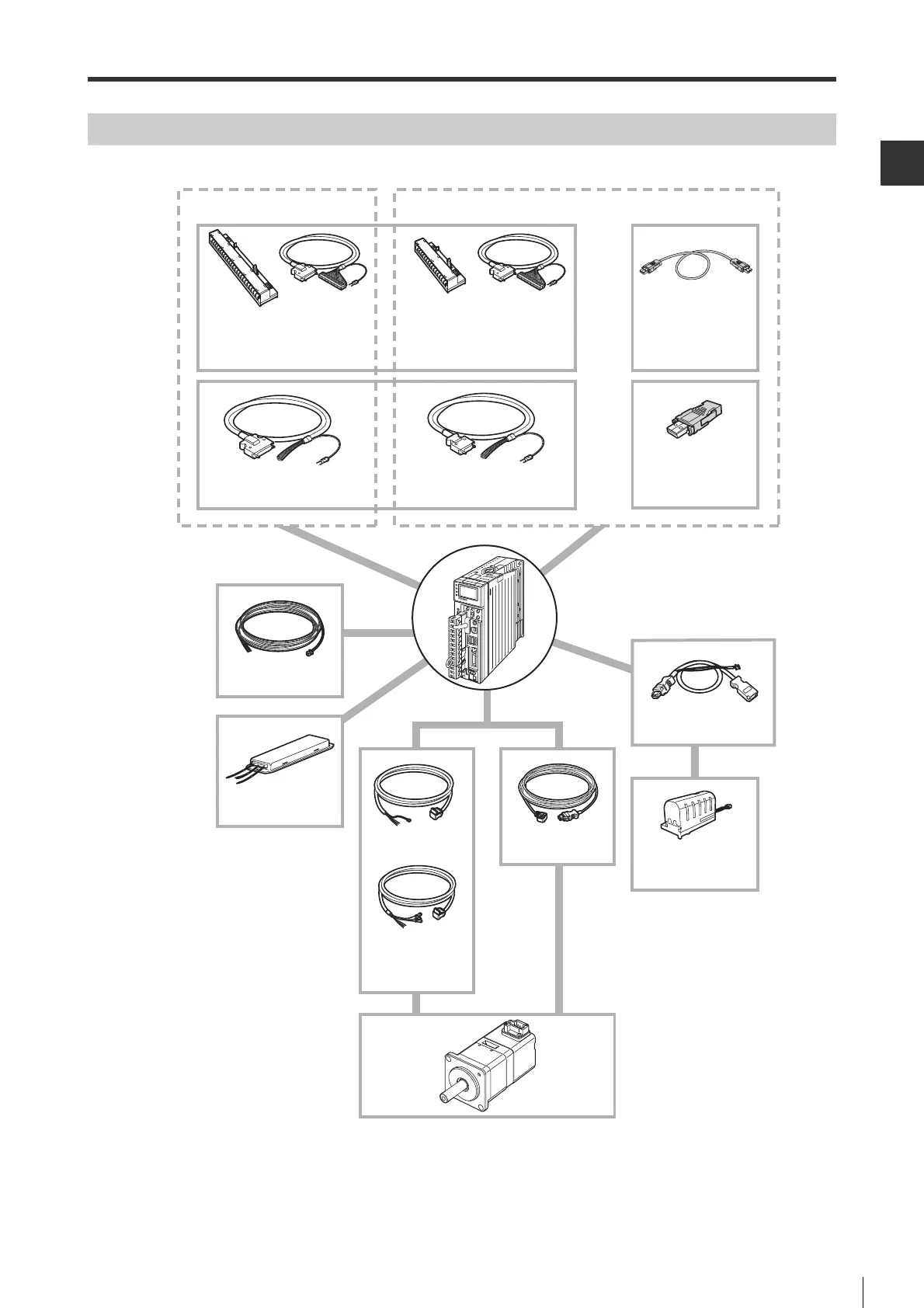
Peripheral Equipment Configuration
The configuration of the SV series AC servo system and peripheral equipment is shown as follows.
*1 For SV-1002/1502/2002/3002/5002, motor power cable and electromagnetic brake power cable
should be separated.
*2 For SV-200*2/SV-300*2/SV-500*2, SV-B1 extension cable (OP-87074) must be used.
Pulse/Analog input type
I/O connector terminal block
I/O connector terminal block cable
I/O connector cable
Analog monitor cable
OP-84408
Encoder cable
SV-Eƶ
Servo motor
SV-Mƶƶƶƶƶ : Standard motor
SV-Bƶƶƶƶƶ : Electromagnetic brake motor
Encoder type A: ABS C: INC
Axis type S: Straight axis K: Axis with keyway
Servo amplifier
SV-ƶƶƶLƶ : MECHATROLINK-II type
SV-ƶƶƶPƶ : Pulse/Analog input type
Branch cable for
battery connecting
OP-84398
Lithium battery with
battery case
SV-B1
Regenerative resistor
OP-84399
OP-87073
(50pin)
OP-84410
(26pin)
OP-84411
MECHATROLINK-II type
MECHATROLINK-II
cable
SV-Lƶ
MECHATROLINK-II
terminator
SV-LT1
(50pin)
OP-84400 (1m)
OP-84401 (3m)
(26pin)
OP-84402 (1m)
OP-84403 (3m)
KV-HC4 KV-HC3
(w/o electromagnetic
brake)
SV-Cƶƶ
(w/ electromagnetic
brake)
SV-Dƶƶ
Motor power cable
 Loading...