2-4
CONFIGURATION & SPECIFICATIONS
- SV Series User’s Manual -
2-2 Names and Functions of Parts
This section describes names and functions of each part of the SV series.
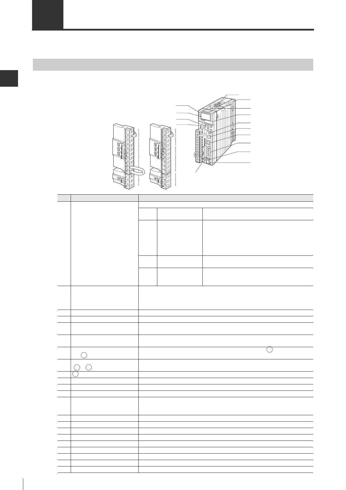
Name and Function of Each Part of the Servo Amplifier
● MECHATROLINK-II type
SV-005L2
(5)
(6)
(7 )
(10)
(11)
(5)
(6)
(7 )
(8)
(9)
(11)
200V type 100V type
(1)
(2)
(3)
(4)
(14)
(15)
(16)
(17)
(18)
(19)
(20)
(21)
(22)
(12)
(13)
For servo amplifiers above 2kW, terminals (5)-(11)
use a screw type terminal block instead of connectors.
No. Name Function
(1) Indicator LED
To indicate status of the servo amplifier.
SV ON Servo ON LED
LED ON : Servo ON status
LED OFF : Servo OFF status
CMD
Command input in
progress LED
LED ON :
Indicates servo ON status for the following conditions:
Position control : Pulse command input status
Speed control
:Speed command input>Zero speed
detection value
Torque control
:
Torque command input>10% rated torque
LED OFF: Other than above conditions
WARN Warning LED
LED blink: Warning occurred
LED OFF: Warning not occurred
COM
MECHATROLINK
communication in
progress LED
LED ON :
MECHATROLINK communication established
LED OFF: MECHATROLINK communication not
established status
(2) Access window
To display the parameter setting and monitor the servo amplifier. The backlight color
indicates operation status.
Green: no alarm occurs
Red : an alarm occurs
(3)
Operation keys of the access window
Used for operation of the access window.
(4) CHARGE LED
Orange LED ON when the amplifier is powered through the power supply of main circuit.
(5)
Power terminal of main circuit
(L1, L2, L3)
To connect the power supply of main circuit. * 100V type(L1, L2)
(6)
Power terminal of control circuit
(L1C, L2C)
To connect the power supply of control circuit.
(7)
Regenerative resistor terminal
(B1/ , B2, B3)
To connect an external regenerative resistor. *100V type(B1/ , B2)
* At 750W to 5kW, B2 and B3 are short-circuited. (internal regenerative resistor)
(8)
DC reactor connection terminal
(1, 2)
To connect DC reactor * unavaicabe for 100V type.
(9) Do not wire this terminal. * Unavailable for 200V type.
(10) N.C. Do not wire this terminal. * Unavailable for 200V type.
(11)
Motor power connector(U, V, W)
To connect power cable of the servo motor.
(12) Protective ground terminal To connect the grounding wire.
(13) Cooling fan
Built-in fan for cooling the servo amplifier. For 750W, 1kW and 400W (100V type)
servo amplifiers, it is mounted on the right side of the servo amplifier, on the top for
1.5kW, on the bottom for the 2kW-3kW, and on the top and right side for the 5kW.
(14) Mounting hole To mount the servo amplifier on the control panel.
(15)
Connector for the analog monitor
Connected with a dedicated cable, used to monitor motor speed and torque command, etc.
(16) Model Type of servo amplifier
(17) Station address setting switch To specify station addresses.
(18) USB connector To connect a PLC.
(19) MECHATROLINK Connector To connect various MECHATROLINK-II equipments.
(20) I/O connector To connect the forced stop button, limit switches and alarm buttons, etc.
(21)
Encoder connector To connect the encoder cable of the servo motor.
(22)
Battery connector To connect the battery when using an absolute position system.
 Loading...