SIGNALS AND WIRING
4-3
- SV Series User’s Manual -
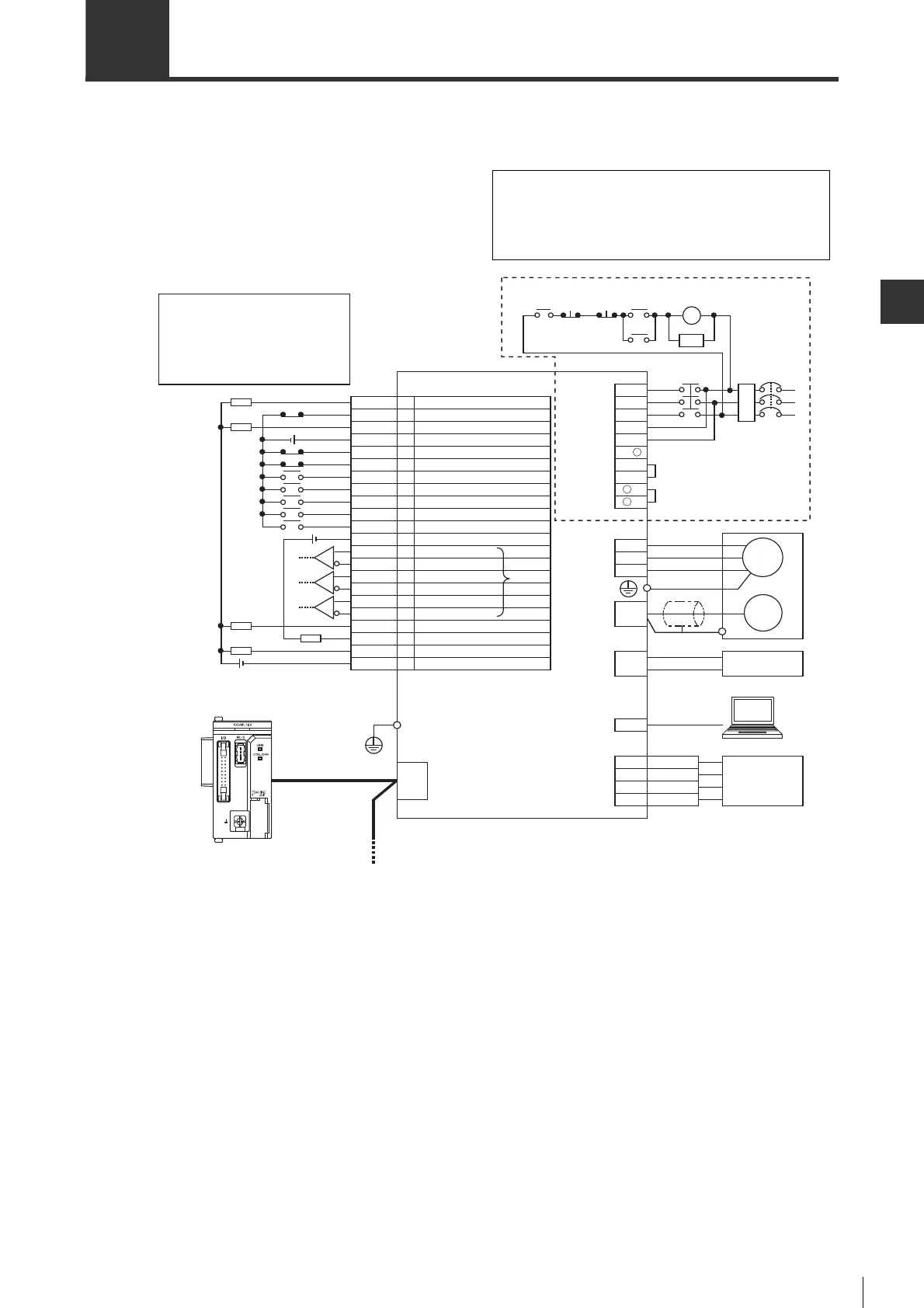
4-2 Standard Wiring Diagram
■ Standard wiring diagram for MECHATROLINK-II type
The typical wiring example of MECHATROLINK-II type is shown as follows.
*1 The differential line driver is equivalent to AM26C31.
*2 Please note the following precautions when wiring for the MECHATROLINK-II cables.
• The cable length between stations (between servo amplifiers, between high-level equipment and servo
amplifier) should be greater than 0.5m.
• The total cable length should be within 50m.
• Please install MECHATROLINK-II terminator (terminal resistance) on the servo amplifiers at both side of the
trunk when connecting multi-servo amplifiers.
*3 The alarm will output for max. 5s when powering on the control loop.
*4 Wiring is different depending on whether to use an external regenerative resistor or a DC reactor.
Emergency
stop
Main
circuit
ON
Main
circuit
OFF
RA
NFB No fuse breakeer
MC Magnetic contactor
SA Surge absorber (surge killer)
M Motor
ENC Encoder
RA Alarm output relay
FIL Noise filter
ALARM
FSTOP
Encoder pulse A phase -
Encoder pulse B phase +
Encoder pulse Z phase open collector
Warning
Output common
Input common (+24 V)
Limit switch positive
External latch signal 1
External latch signal 2
Encoder pulse Z phase +
Encoder pulse Z phase -
Operation ready
Encoder pulse B phase -
Origin return deceleration switch
Negative torque limit selection
Signal ground
Encoder pulse A phase +
ZOC
Z
-
WARN
RDY
COM1
A+
B+
A
-
B
-
Z+
DEC
LSP
NTL
EXT1
EXT2
1
2
3
6
7
8
9
10
11
12
13
16
17
18
19
20
21
22
23
24
25
26
Electromagnetic brake timing
Forced stop
BRAKE
Alarm
Limit switch negative
Positive torque limit selection
SG
LSN
COM0+
PTL
MECHATROLINK
connector
Protective ground terminal
Encoder
connector
Motor
power
supply
connector
Battery
connector
USB
connector
Main circuit/
controlcircuit
power supply
connector
*3
Analog
monitor
connector
I/O connector
AC 200V type servo amplifier
RA
MECHATROLINK-II
NFB
FIL
*2
MC
SA
B2
B3
R
S
T
L2
L1C
L3
L2C
MC
L1
B1/
+
-
1
-
2
*1
MC
VTG
SG
Measuring instrument, etc.
+
Servo motor
Lithium battery with battery housing
PC
-
4
1
3
2TMON
SG
M
ENC
U
V
W
*4
24V
24V
24V
Wiring is different when using power supplies of AC
100V, single-phase AC 200V and DC200V. Please see
"Wiring the Main Circuit/Control Circuit and Motor Power
Supply Connector", Page 4-7.
 Loading...