4-40
SIGNALS AND WIRING
- SV Series User’s Manual -
4-7 Wiring Analog Monitor
This section describes how to wire the analog monitor.
Analog Monitor Specifications
Specifications of analog monitor are as follows.
■ Analog monitor cable (OP-84408)
Wire size : AWG#24 UL-Style No.1007 * Be sure to use the same cable color as in the table.
Socket : DF11-4DS-2C (HIROSE)
Contact : DF11-2428SCF (HIROSE)
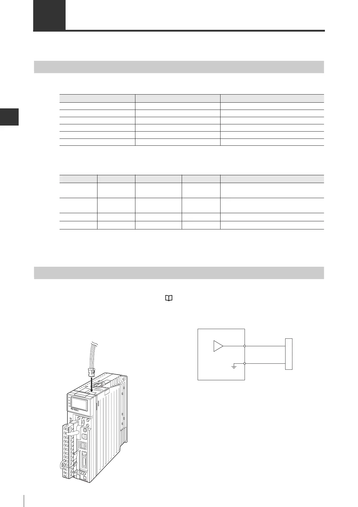
Connecting Analog Monitor Connector
To connect the analog monitor cable (OP-84408) with the analog monitor connector at the top of the servo amplifier.
For analog monitor setting/monitor signal, see "5-6 Analog Monitor Setting", page 5-31.
● Connecting with servo amplifier ● Connecting with measuring instruments
Item Specification Remark
Number of chs 2ch
Output range
-
10V to +10V Linear valid range is within ±8V.
Resolution 16bit
Conversion precision
±20mV
Standard value
Max. permissible load current
±1mA
Conversion speed 1.2ms Standard value
Terminal No.
Terminal name
Function name Cable color Function Description
1 VTG Analog monitor 2 Red
Used for monitoring values set in "Analog
monitor 2" (OTH_16).
2 TMON Analog monitor 1 White
Used for monitoring values set in "Analog
monitor 1" (OTH_15).
3 SG - Black Signal ground
4 SG - Black Signal ground
Servo amplifier
VTG, TMON
SG
Measuring instruments
Open the protective cover of the analog monitor
connector at the top of servo amplifier, and connect the
analog monitor cable (OP-84408).
 Loading...