5-20
5-3 I/O Signal Setting
- SV Series User’s Manual -
COMMON PARAMETER SETTING
Pulse/analog input type
■ Input signal
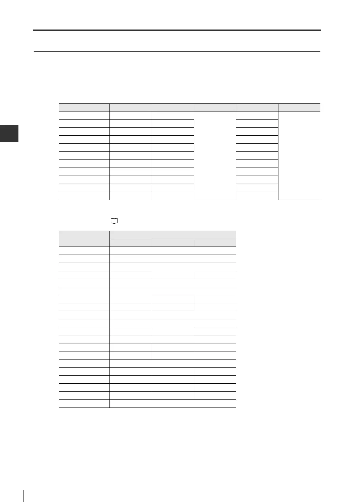
● Signal assignment
The following input signals can be assigned to pin No. 20-24/41-46. Signal assignment can be set through a
parameter.
The input signals that can be set and corresponding set value are shown below.
For input signals, see "4-5 Wiring I/O Signals", Page 4-24.
Signal name Pin No. Parameter type Setting range Default Enable timing
IN1 20 IO_01
0 to 19
11
After power is ON
again
IN2 21 IO_02 12
IN3 22 IO_03 19
IN4 23 IO_04 7
IN5 24 IO_05 1
IN6 41 IO_06 6
IN7 42 IO_07 8
IN8 43 IO_08 9
IN9 44 IO_09 2
IN10 45 IO_10 4
IN11 46 IO_11 5
Set value
Assigned function
Position control
Speed control Torque control
0 -
1 SVON
2 RESET
3 PCN PCN -
4 PTL
5 NTL
6 - ST1 RS1
7 - ST2 RS2
8 LSP
9 LSN
10 GAIN GAIN -
11 - SPD1 SPD1
12 - SPD2 SPD2
13 - SPD3 SPD3
14 CSEL
15 GEAR1 - -
16 GEAR2 - -
17 INHIBIT - -
18 - ZCLAMP -
19 SEN
 Loading...