5-18
COMMON PARAMETER SETTING
- SV Series User’s Manual -
5-3 I/O Signal Setting
I/O Signal Assignment and Polarity Setting
I/O terminal are assigned a function in advance, and some terminals can be assigned other functions or polarity of
them can be changed. Function assignement/polarity setting can be performed through a parameter.
• Same function cannot be assigned to several output terminals. When a duplicate setting exists, the
"*Parameter setting error 0" alarm (040) will occur.
• Same function can be assigned to several input terminals.
• I/O signal assignment/polarity can be set through a parameter. To enable a setting, be sure to make
power ON again or restart the servo amplifier.
• Set input polarity of the "Forced stop (FSTOP)" signal to "N.C." to ensure safety.
• Set input polarity of the "Forward limit switch (LSP)" and "Reversal limit switch (LSN)" signal to "N.C." as
much as possible to ensure safety.
• When KV-ML16V is used in combination with the MECHATROLINK-II type servo amplifier, polarity of the
"Origin return deceleration switch (DEC)" should be set to a polarity reverse to the KV-ML16V origin
sensor; polarity of the "External latch signal 1 (EXT1)" signal should be set to the same polarity of the KV-
ML16V origin sensor.
MECHATROLINK-II type
■ Input signal
● signal assignment
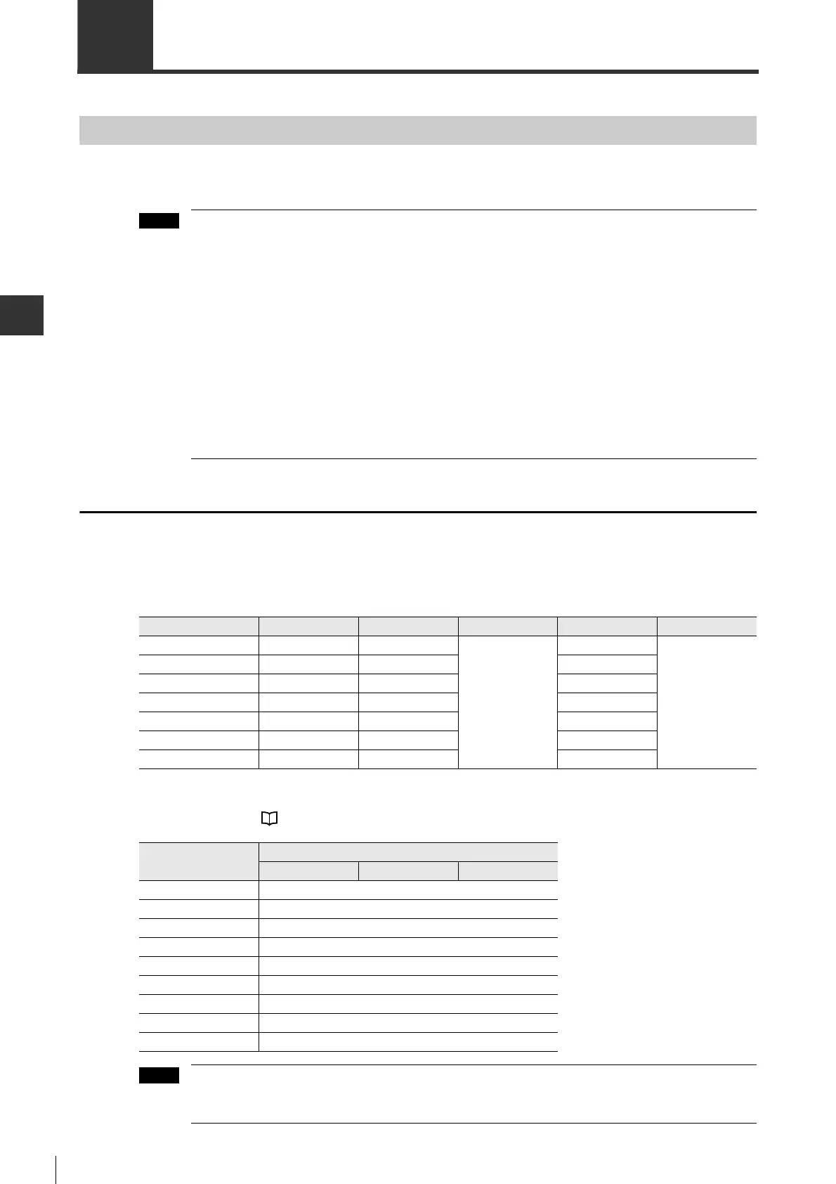
The following input signals can be assigned to pin No.7 to 13. Signal assignment can be set through parameters.
The input signals that can be set and corresponding set value are shown below.
For input signals, see "4-5 Wiring I/O Signals", Page 4-24.
Set value 4 to 6 cannot be assigned to terminals other than IN4 to IN6. When 4 to 6 is set for terminals
other than IO_40 to 42, the "*Parameter setting error 0" alarm (040) will occur.
Signal name Pin No. Parameter type Setting range Default Enable timing
IN1 7 IO_37
0 to 8
1
After power is ON
again
IN2 8 IO_38
2
IN3 9 IO_39
7
IN4 10 IO_40
4
IN5 11 IO_41
5
IN6 12 IO_42
3
IN7 13 IO_43
8
Set value
Assigned function
Position control
Speed control Torque control
0 -
1 LSP
2 LSN
3 DEC
4 EXT1
5 EXT2
6 EXT3
7 PTL
8 NTL
 Loading...