2-9
2-3 Servo Amplifier Specifications
CONFIGURATION & SPECIFICATIONS
- SV Series User’s Manual -
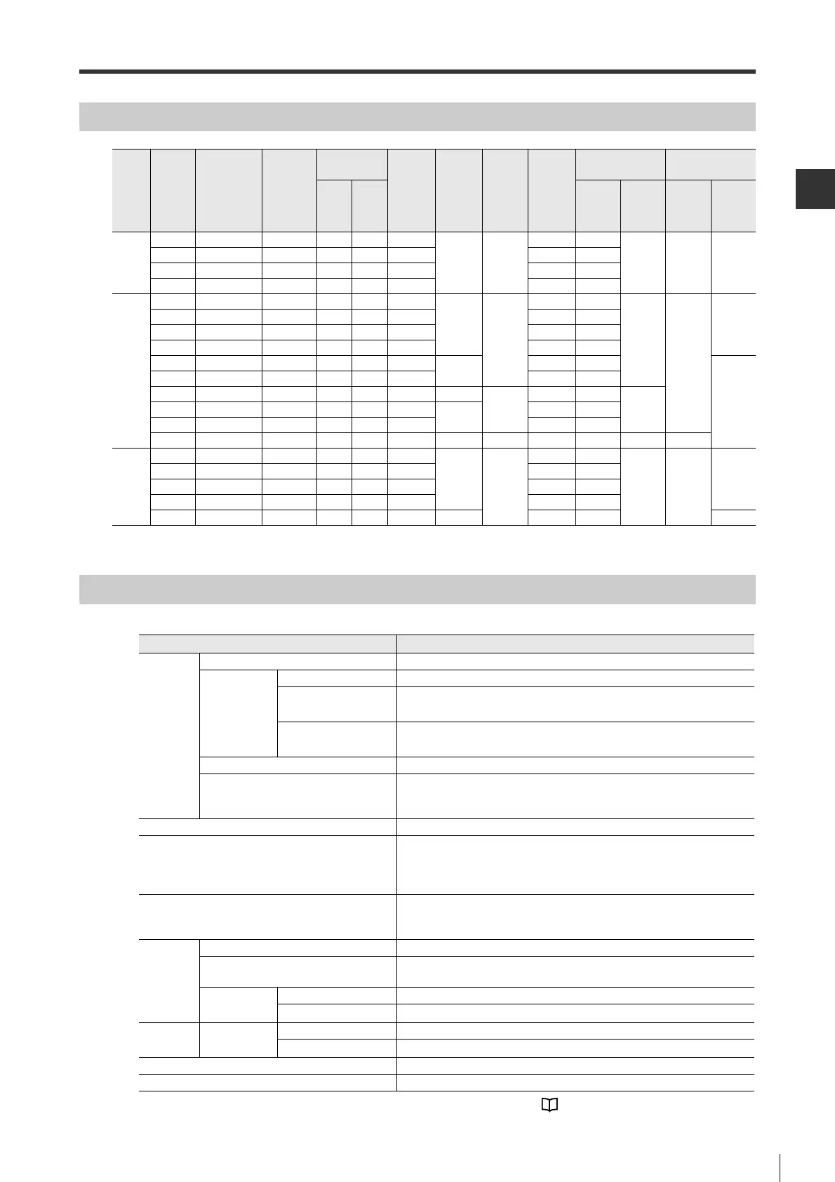
Power Supply/Current Capacity and Power Loss
*
When the above current is used, the duration of the incoming current is 20 ms at maximum.
Performance Specifications
Main
circuit
power
supply
Maximum
applied
motor
capacity
(W)
Model
Power
supply
capacity
(VA) per
unit
Output current
(Ams)
Main
circuit
power
loss
(W)
Built-in
regene-
rative
resistor
power
loss
(W)
Control
circuit
power
loss
(W)
Total
power
loss
(W)
Input rated
current
Incrush current
*
Conti-
nuous
Maxi-
mum
Main
circuit
(Arms)
Control
circuit
(Arms)
Main
circuit
(A)
Control
circuit
(A)
Single
phase
100 V
50 SV-0051 200 0.66 2.1 5.4
-17
22.4 1.5
0.38 16.5 35
100 SV-0101 300 0.91 2.9 7.8 24.8 2.5
200 SV-0201 700 2.1 6.5 14.4 31.4 5
400 SV-0401 1400 2.8 9.3 25.6 42.6 10
3-
phase
200 V
50 SV-0052 200 0.66 2.1 5.1
-
17
22.1 1
0.2
33
70
100 SV-0102 300 0.91 2.9 7.3 24.3 1
200 SV-0202 600 1.6 5.8 13.5 30.5 2
400 SV-0402 1000 2.8 9.3 24 41 3
750 SV-0752 1600 5.5 16.9 43.8
8
68.8 6
33
1.0k SV-1002 2300 7.6 17 53.6 78.6 6
1.5k SV-1502 3200 11.6 28 65.8 10
22
97.8 7.3
0.252.0k SV-2002 4000 18.5 42 111.9
16
149.9 9.7
3.0k SV-3002 5900 19.6 56 113.8 151.8 15
5.0k SV-5002 7500 32.9 84 263.7 36 27 326.7 25 0.3 65.5
Single
phase
200 V
50 SV-0052 200 0.66 2.1 5.2
-
17
22.2 2
0.2 33
70
100 SV-0102 300 0.91 2.9 7.4 24.4 2
200 SV-0202 700 1.6 5.8 13.7 30.7 3
400 SV-0402 1200 2.8 9.3 24.9 41.9 5
750 SV-0752 1900 5.5 16.9 52.7 8 77.7 9 33
Item Specifications
Performance
Speed control range
1:5000 (Under the condition when rated torque is greater than load torque)
Speed
fluctuation
rate
When the load fluctuates
±0.01% max. with a load fluctuation from 0 to 100% (at rated rotation speed)
When the main circuit
voltage fluctuates
0% with the rated voltage fluctuation of ±10% (at rated rotation speed)
When the ambient
temperature fluctuates
±0.1% max. at an ambient temperature between 0 and +50°C (at rated
rotation speed)
Torque control accuracy(repeatability) ±1%
Speed frequency response
1.6 kHz (when JL = JM)
*JL: Motor shaft converted load at moment of inertia, JM: Motor
moment of inertia
Dynamic brake Incorporated
Regenerative resistor
Built-in regenerative resistor : 50 W to 400 W models: Not provided
750 W model: Provided
External regenerative resistor : OP-84399(50Ω : 50W to 1.0kW)
OP-87073(20Ω : 1.5kW
*1
)
*1 2kW to 5kW can also be used depending on operational conditions. "5-4 Regenerative Resistor Setting",
Page 5-23
Analog monitor output for observation
Built-in monitor output for monitoring motor rotation speed/torque
command, etc.
No. of channels: 2
Display
function
Access window Status monitor, parameter setting, tuning, etc.
CHARGE LED indicator
CHARGE LED indicator (orange) for indicating the main circuit power
supply input
Status
indicator
Pulse/analog input type
Servo ON, command input, warning
MECHATROLINK-II type
Servo ON, command input, warning, MECHATROLINK communication
Communication
function
USB
communication
Connection device Personal computer
Function Status display, parameter setting, tuning, etc
Protective functions
Overcurrent, overvoltage, low voltage, overload, regeneration error, etc.
Other functions Automatic tuning, absolute position system, etc.
 Loading...