4-6
SIGNALS AND WIRING
- SV Series User’s Manual -
4-3
Wiring the Power Supply of Main/Control Circuit
This section describes how to wire main/control circuit power cables.
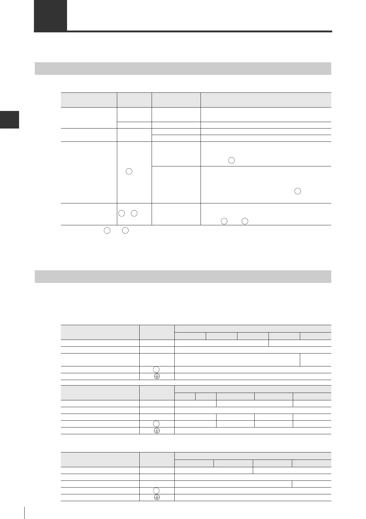
Terminal Name and Function List
Names and functions of power terminals of main/control circuit are as follows.
Wire Size
This section describes the wire sizes that are used for the servo amplifier main circuit.
■ 200 V model
■ 100 V model
Terminal part name
Terminal
symbol
Model Function and rating
Main circuit power
supply terminal
L1, L2, L3
SV-□□□□2
3-phase (or single-phase
*3
), 200 to 230 VAC,
+10 to -15%, 50/60 Hz
L1, L2
SV-□□□□1
Single-phase, 100 to 115 VAC, +10 to -15%, 50/60 Hz
Control circuit power
supply terminal
L1C, L2C
SV-□□□□2
Single-phase, 200 to 230 VAC, +10 to -15%, 50/60 Hz
SV-□□□□1
Single-phase, 100 to 115 VAC, +10 to -15%, 50/60 Hz
Regenerative resistor
connection terminal
B1/ , B2
*1
*1 Terminals B1/ and 2 of the 200 V type servo amplifier are used for the main circuit power supply terminal when
using a DC power supply.
SV-005□□
SV-010□□
SV-020□□
SV-040□□
When the regenerative capacity is not sufficient, connect
the optional external regenerative resistor between
terminal B1/ and B2.
SV-075□2
SV-100□2
SV-150□2
SV-200□2
SV-300□2
SV-500□2
When the capacity of amplifier regenerative resistor is
insufficient, open B2-B3 and connect an optional external
regenerative resistor between terminal B1/ and B2.
DC reactor
1, 2
*1*2
*2 Not applicable for the 100 V type servo amplifier.
*3 SV-100□2/150□2/200□2/300□2/500□2 use only three-phase power supply.
SV-□□□□2
When the control measures for the high-frequency power
supply are necessary, connect a DC reactor between
terminal 1 and 2.
Terminal part name
Terminal
symbol
SV Series servo amplifier
50 W 100 W 200 W 400 W 750 W
Main circuit power supply input L1, L2, L3 HIV1.25 (AWG16) HIV2.0 (AWG14)
Control power supply input
L1C, L2C HIV1.25 (AWG16)
Motor connection U, V, W HIV1.25 (AWG16)
HIV2.0
(AWG14)
External regenerative resistor connection
B1/ , B2 HIVI.25 (AWG16)
Ground terminal HIV2.0 (AWG14)
Terminal part name
Terminal
symbol
SV Series servo amplifier
1.0kW 1.5kW 2.0kW 3.0kW 5.0kW
Main circuit power supply input L1, L2, L3 HIV2.0(AWG14) HIV3.5(AWG12) HIV5.5(AWG10)
Control power supply input
L1C, L2C HIV1.25(AWG16)
Motor connection U, V, W HIV2.0(AWG14) HIV3.5(AWG12) HIV5.5(AWG10) HIV8.0(AWG8)
External regenerative resistor connection
B1/ , B2 HIV1.25(AWG16) HIV2.0(AWG14) HIV3.5(AWG12) HIV5.5(AWG10)
Ground terminal HIV2.0(AWG14)
Terminal part name
Terminal
symbol
SV Series servo amplifier
50 W 100 W 200 W 400 W
Main circuit power supply input L1, L2 HIV1.25 (AWG16) HIV2.0 (AWG14)
Control power supply input
L1C, L2C HIV1.25 (AWG16)
Motor connection U, V, W HIV1.25 (AWG16) HIV2.0 (AWG14)
External regenerative resistor connection
B1/ , B2 HIV1.25 (AWG16)
Ground terminal HIV2.0 (AWG14)
 Loading...