4-5
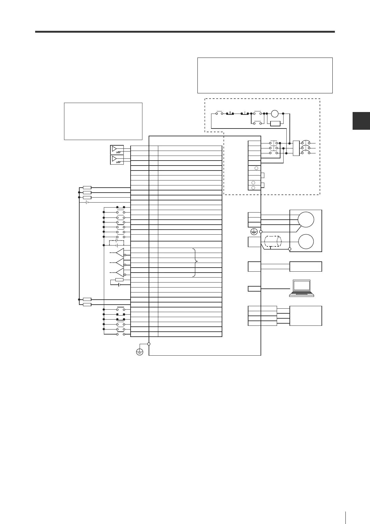
4-2 Standard Wiring Diagram
SIGNALS AND WIRING
- SV Series User’s Manual -
● Speed control/Torque control(When 3-phase AC200V power supply is used)
*1 Differential line driver equivalent to AM26C31.
*2 SG (signal ground) is short-circuited internally.
*3 The function name for speed control. In torque control mode, the name in parentheses is used.
*4 In speed control mode, the function is changed to torque feed forward by parameter setting.
*5 The alarm will output for max. 5s when powering on the control loop.
*6 Wiring is different depending on whether to use an external regenerative resistor or a DC reactor.
NFB No fuse breakeer
MC Magnetic contactor
SA Surge absorber (surge killer)
M Motor
ENC Encoder
RA Alarm output relay
FIL Noise filter
COM1
VCMP(-)
TLM(VLM)
SG
ALARM
COM0
A+
-
SVON
-
ST2(RS2)
-
-
SPD2
FSTOP
V-REF
SG
T-REF
A
-
Z+
B
-
-
SEN
ZSP
ST1(RS1)
RDY
B+
NTL
ZOC
SG
Z
-
RESET
PTL
LSN
LSP
-
-
SPD1
I/O connector
Analog torque limit (Analog torque command) *6 *7
Signal ground *5
Analog speed command (Analog speed limit) *6
Unused
Unused
Unused
Unused
Signal ground *5
Operation ready
Encoder pulse Z phase +
Reverse start (Reverse selection) *6
Absolute position data request
Servo ON
Encoder pulse B phase -
Encoder pulse Z phase -
Limit switch negative
Alarm reset
Zero speed detection
Forward start (Forward selection) *6
Limit switch positive
Output common
Velocity match (Unused) *6
Encoder pulse Z phase open collector
Signal ground *5
Encoder pulse A phase +
Negative torque limit selection
Speed selection 1
Encoder pulse A phase -
Encoder pulse B phase +
Alarm
Speed selection 2
Unused
Forced stop
Limiting torque (Limiting speed) *6
Positive torque limit selection
Unused
Unused
Input common
NFB
Servo motor
*1
Emergency
stop
MC
SA
*2
MC
Analog
monitor
connector
Protective ground terminal
AC 200V type servo amplifier
T
FIL
R
S
Main circuit/
controlcircuit
power supply
connector
*3
Lithium battery with battery housing
+
-
Battery
connector
TMON
SG
2
4
PC
USB connector
Measuring instrument
VTG
SG
1
3
V
W
Encoder
connector
Motor power
supply
connector
U
M
ENC
MC
Main
circuit
ON
3
4
5
6
7
8
10
11
14
15
16
17
18
19
20
21
22
23
*4
Main
circuit
OFF
RA
B2
B3
L2
L1C
L3
L2C
L1
B1/
+
-
1
-
2
RA
24V
24V
24V
26
27
28
29
30
31
32
33
34
35
38
39
41
42
43
44
45
46
24
25
Wiring is different when using power supplies of AC
100V, single-phase AC 200V and DC200V. Please see
"Wiring the Main Circuit/Control Circuit and Motor Power
Supply Connector", Page 4-7.
 Loading...