4-24
SIGNALS AND WIRING
- SV Series User’s Manual -
4-5 Wiring I/O Signals
This section describes how to wire I/O connectors.
For assignment and polarity setting of I/O signal, see "5-3 I/O Signal Setting", page 5-18.
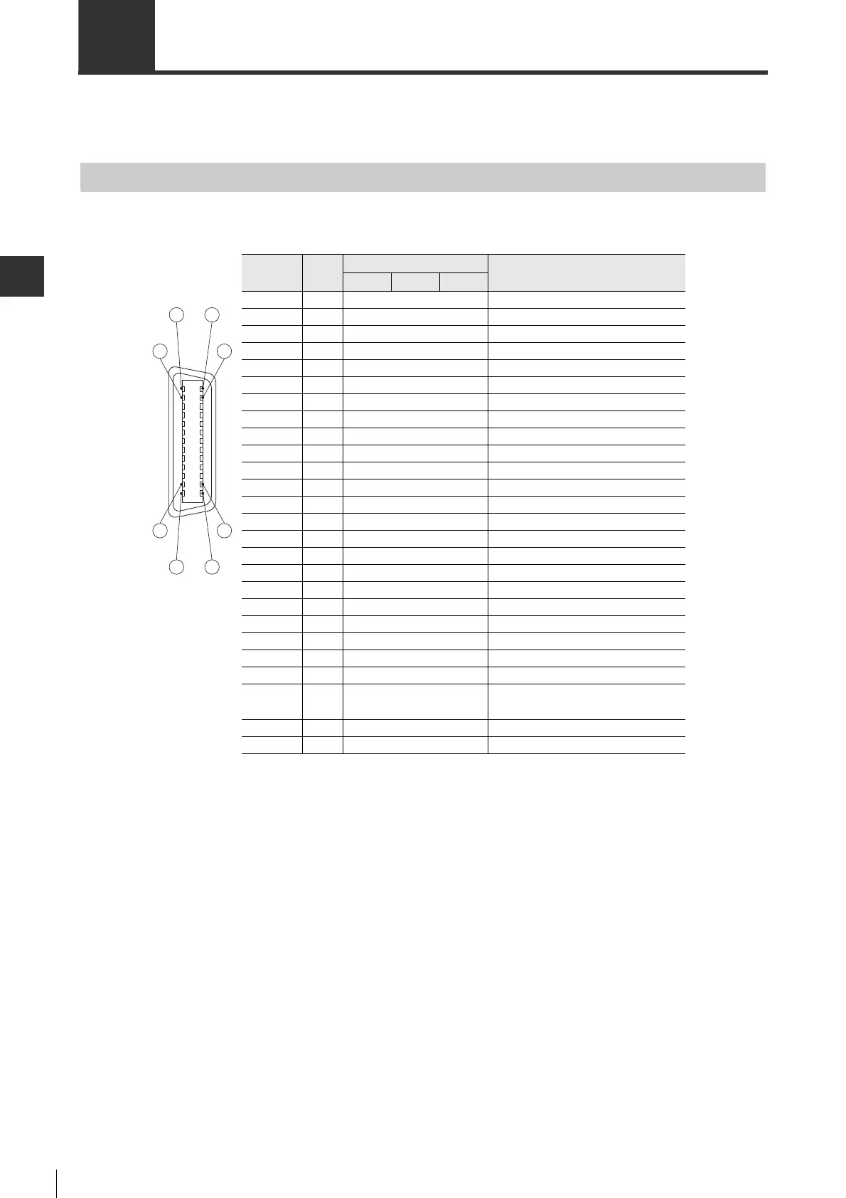
Pin Assignment of I/O connector
■ MECHATROLINK-II type
Pin No. I/O
Terminal
Name
P
osition
Speed
Torque
1 Output BREAK Electromagnetic brake timing
2 Input FSTOP Forced stop
3 Output ALARM Alarm
4- - -
5- - -
6 - COM0+ Input common (+24V input)
7 Input LSP Forward limit switch
8 Input LSN Reversal limit switch
9 Input PTL Forward torque limit selection
10 Input EXT1 External latch signal1
11 Input EXT2 External latch signal2
12 Input DEC Origin return deceleration switch
13 Input NTL Reversal torque limit selection
14 - - -
15 - - -
16 - SG Signal ground
17 Output A+ Encoder pulse A-phase +
18 Output A
-
Encoder pulse A-phase
-
19 Output B+ Encoder pulse B-phase +
20 Output B
-
Encoder pulse B-phase
-
21 Output Z+ Encoder pulse Z-phase +
22 Output Z
-
Encoder pulse Z-phase
-
23 Output RDY Ready to operate
24 Output ZOC
Open collector of encoder pulse
Z-phase
25 Output WARN Warning
26 - COM1 Output common
14
152
1
26
2512
13
Connector view seen
from the outer side of
SV series
 Loading...