4-23
4-4 Wiring Servo Motor
SIGNALS AND WIRING
- SV Series User’s Manual -
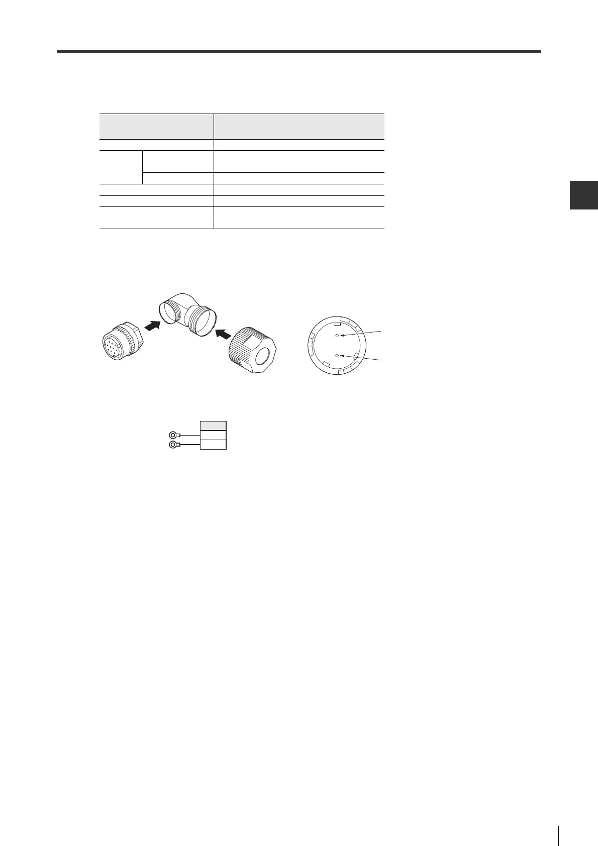
■Electromagnetic brake power cable (1kW to 5kW)
● Components and specifications
● How to wire
For wiring method at servo motor side, see " Encoder Cable", page 4-15.
For wiring electromagnetic brake, see " Electromagnetic Brake", page 4-17.
● Wiring diagram
Electromagnetic brake
connector
Servo motor side (Fig. (7))
Vendor DDK Ltd.
Used
components
Connector kit
CM10-AP2S-M-D(angle) (welding)
CM10-SP2S-M-D(straight) (welding)
Contact CM10-#22SC(S2)-100
Supported wire size AWG #16 MAX
Supported wire O.D. φ 6.0 to 9.0mm
User's Manual
TC-610(angle)
TC-609(straight)
Connector welding surface view
Servo amplifier side
Power supply for
electromagnetic brake
Pin No.
1
2
 Loading...