4-22
SIGNALS AND WIRING
4-4 Wiring Servo Motor
- SV Series User’s Manual -
■Motor power cable (1kW to 5kW)
● Components and specifications
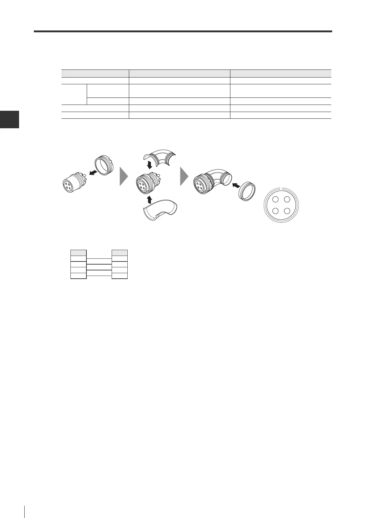
● How to wire
The wires at servo amplifier side adopts barbed wires,while the connector at servo motor side is soldered.
● Wiring diagram
Motor power connector For 1kW/1.5kW/2kW(Fig. 6) For 3kW/5kW
Vendor Japan Aviation Electronics Industry Ltd. Japan Aviation Electronics Industry Ltd.
Used
components
Plug
N/MS3108B18-10S(angle) (welding)
N/MS3106B18-10S(straight) (welding)
N/MS3108B22-22S(angle) (welding)
N/MS3106B22-22S(straight) (welding)
Cable clamp N/MS3057-10A N/MS3057-12A
Supported wire size AWG #12 MAX AWG #8 MAX
Internal rubber brushing I.D. φ 14.3mm φ 15.9mm
D
C
A
B
Connector welding surface view
Servo amplifier side Servo motor side
Signal name
U phase
V phase
W phase
FG
Pin No.
A
B
C
D
 Loading...