A-42
APPENDIX
A-5MECHATROLINK-II Communication Commands
- SV Series User’s Manual -
Operation Flow
Operation methods
Be sure to check the communication "6-2 SV Series Setting", Page 6-3 before starting communication.
There are two methods when operating motor via MECHATROLINK-II communication commands. One method is
through managing the control equipment, and the other is through managing the servo amplifier.Parameters for servo
amplifier are not necessary to set up again when managing parameters via control equipment and replacing the servo
amplifier.
The respective operation flows are as follows.
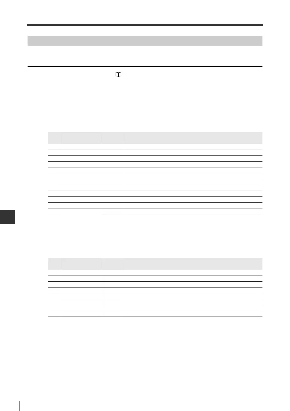
■Operation sequence for managing parameters via control equipment
*1 In case the connection cannot be cut off, send DISCONNECT command for at least two periods, then send
CONNECT command.
■Operation sequence for managing parameters via servo amplifier
● Installation
*1 In case the connection cannot be cut off, send DISCONNECT command for at least two periods, then send
CONNECT command.
*2 PRM_WR cannot be used.
Steps
Command
Command
code
Steps
1 - - Turn on the power of main circuit/control circuit.
2 DISCONNECT
*1
0FH Disconnect the previous connection.
3 CONNECT 0EH Establish connection and start watchdog timer.
4 ID_RD 03H To read the ID of servo motor.
5 PRM_RD 01H To read parameters of servo motor.
6 PRM_WR 02H To read parameters and other setting info of servo motor.
7 CONFIG 04H To write parameters required for servo motor.
8 SENS_ON 23H Turn on the power of encoder to capture the position data.
9 SV_ON 31H Set the servo motor to servo ON status.
10 SV_OFF 32H Set the servo motor to servo OFF status.
11 DISCONNECT 0FH Disconnect the communication connection.
12 - - Trun off the power of main circuit/control circuit.
Steps
Command
Comman
d code
Steps
1 - - Turn on the power of main circuit/control circuit.
2 DISCONNECT
*1
0FH Disconnect the previous connection.
3 CONNECT 0EH Establish connection and start watchdog timer.
4 ID_RD 03H To read the ID of servo motor.
5 PRM_RD 01H To read parameters of servo motor.
6 PPRM_WR
*2
1CH To write parameters required for servo motor to internal memory.
7 DISCONNECT 0FH Disconnect the communication connection.
8 - - Trun off the power of main circuit/control circuit.
 Loading...