7-11
- SV Series User’s Manual -
PARAMETER SETTING AND OPERATION OF PULSE/ANALOG INPUT
7-4 Speed Control
In the speed control mode, a specified speed is applied on the servo motor by inputting an analog voltage signal or
speed command into the servo amplifier.
Rotation direction is switched through the "Forward start (ST1)"/"Reversal start (ST2)" input.
In speed control, the speed command can be adjusted with the speed command soft start used for smoothing speed
command or with the gain settings/filter settings/offset adjustment of analog speed input.
Additionally, the following functions are also available: the torque limit function which keeps the torque within a certain
range; the "Velocity match (VCMP)" signal which detects whether the specified speed is reached; as well as the zero
clamp function which executes servo lock when the motor drops below a certain speed.
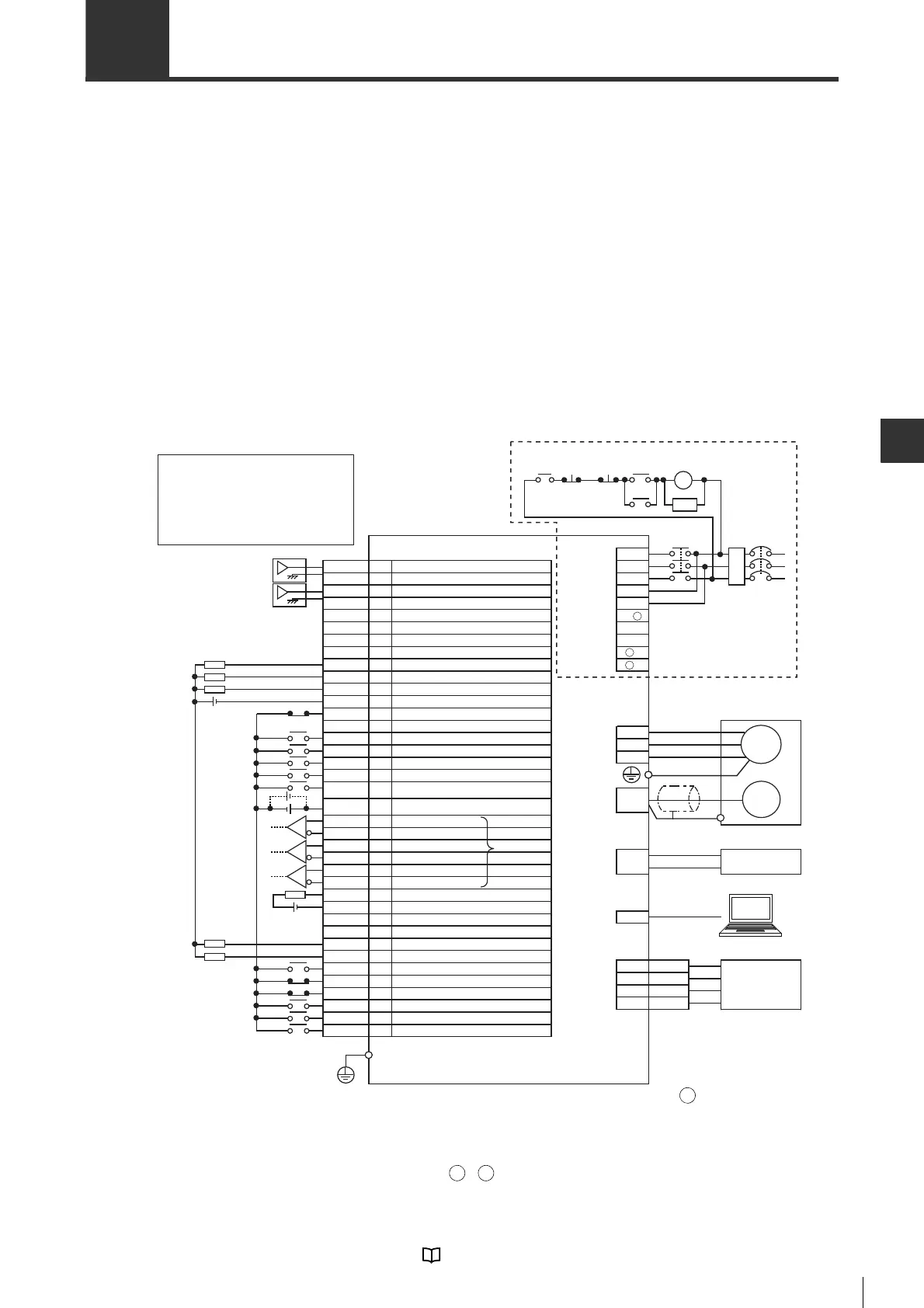
■ Pin assignment and wiring
For speed control mode, the following wiring diagram can be used.
Wiring is different when using power supplies of AC 100V,
single-phase AC 200V and DC200V. Please see
"Wiring
the Main Circuit/Control Circuit and Motor Power Supply
Connector", page 4-7
.
*1 When an external regenerative resistor is used, the same is connected between B1/ -B2. SV-075P2/100P2/
150P2/200P2/300P2/500P2 has a built-in regenerative resistor. B2 and B3 are short-circuited. The wire
between B2 and B3 should be disconnected before the external regenerative resistor is connected.
*2 These are short-circuited when delivered. No polarity needs to be considered when connecting a DC reactor.
*3 The AC100V type servo amplifier has no L3/ 1/ 2 terminals..
*4
The differential line driver is equivalent to AM26C31.
*5 SG (signal groud) is short-circuited internally.
*6 During the speed control process, depending on parameter settings, this goes to the torque feedforward mode.
For wiring and I/O terminal specification, see "4-5 Wiring I/O Signals", Page 4-24.
NFB No fuse breakeer
MC Magnetic contactor
SA Surge absorber (surge killer)
M Motor
ENC Encoder
RA Alarm output relay
FIL Noise filter
COM1
VCMP
TLM
SG
ALARM
COM0
A+
ˉ
SVON
ˉ
ST2
ˉ
ˉ
SPD2
FSTOP
V-REF
SG
T-REF
A
-
Z+
B
-
ˉ
SEN
ZSP
ST1
RDY
B+
NTL
ZOC
SG
Z
-
RESET
PTL
LSN
LSP
ˉ
ˉ
SPD1
I/O connector
Analog torque limit *6
Signal ground *5
Analog speed command
Unused
Unused
Unused
Unused
Signal ground *5
Operation ready
Encoder pulse Z phase +
CW start
Absolute position data request
Servo ON
Encoder pulse B phase -
Encoder pulse Z phase -
Limit switch negative
Alarm reset
Zero speed detection
CCW start
Limit switch positive
Output common
Speed matching
Encoder pulse Z phase open collector
Signal ground *5
Encoder pulse A phase +
Negative torque limit selection
Speed selection 1
Encoder pulse A phase -
Encoder pulse B phase +
Alarm
Speed selection 2
Unused
Forced stop
Limiting torque
Positive torque limit selection
Unused
Unused
Input common point
NFB
Servo motor
*1
Emergency
stop
MC
SA
*2
MC
Analog
monitor
connector
Protective ground terminal
AC 200V type servo amplifier
T
FIL
R
S
Main circuit/
controlcircuit
power supply
connector
*3
Lithium battery with battery housing
+
-
Battery
connector
TMON
SG
2
4
PC
USB
connector
Measuring instrument
VTG
SG
1
3
V
W
Encoder
connector
Motor power
supply
connector
U
M
ENC
MC
Main
circuit
ON
3
4
5
6
7
8
10
11
14
15
16
17
18
19
20
21
22
23
*4
Main
circuit
OFF
RA
B2
B3
L2
L1C
L3
L2C
L1
B1/
+
-
1
-
2
RA
24V
24V
24V
26
27
28
29
30
31
32
33
34
35
38
39
41
42
43
44
45
46
24
25
 Loading...