18
- SV Series User’s Manual -
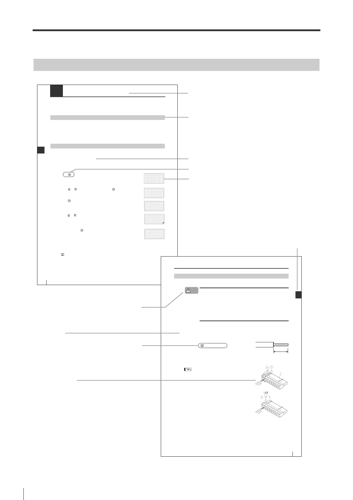
Conventions Used In This Manual
The following shows how pages are configured, and the symbols and terminology used in this Manual.
Page Configuration and Symbols
- SV Series User’s Manual -
8-3 Switching to Manual Tuning
In case you cannot get your desired effect through auto tuning, you can switch to manual tuning such as gain tuning
PRO/gain search PRO. In this case, you need perform "auto tuning parameter mapping" and "calcualtion of moment
of inertia ratio".
Auto Tuning Parameter Mapping
Gain settings derived from auto tuning are mapped to servo parameters.
Such parameters include position control gain, speed control gain and integral time constant.
This function is enabled in the position control mode and speed control mode and disabled in the torque control mode.
In addition, "tuning mode" is only enabled in the "auto tuning" mode.
Steps to follow
Please take the following steps for auto tuning parameters mapping.
Ƶ Tuning with Access Window
Please take the following steps when you use the Access Window for auto tuning.
For how to operate Access Window, see Chapter 11 "Access Window"
1
Press " " to display the main menu.
2
Press " "/ " " to select "2.Tuning". Then, press " ".
Display submenu
3
Press " ".
4
Press " " /" " key to display the "Reflect OK?" screen.
5
Press and hold the " " key (for more than 1s) until you see "Done".
Ƶ Tuning with the KV-ML/MC setup tool (KV MOTION+)/SV series setup software
For how to operate KV-ML/MC setup tool (KV MOTION+)/SV series setup software, see the following manuals.
KV-ML/MC setup tool User's Manual, Chapter 7 "SV Monitor"
SV series setup software User's Manual, Chapter 6 "SV Monitor"
1.モニタ
2.チューニング
3.パラメータ
4.アラーム
1.オート/マニュアル
チューニング
*チューニングモード
オート
チューニング
ATパラメータハンエイ
チューニング
ATパラメータハンエイ
カンリョウ
Headline
Indicates the main content of the chapter.
Mid-heading
Mid-heading is the title that further classify the headline.
Sub-heading
Operation keys of the Access Window.expressed by ""
Operation screens of the Access Window.
4-7
4-3
Wiring the Power Supply of Main/Control Circuit
SIGNALS AND WIRING
- SV series User’s Manual -
How to Wire Power Connector Wiring Method of Main/Control Circuit
Wiring for power connector main/control circuit of is described as follows.
W
hen wiring power connector of main/control circuit , please be sure to abide by the followings.
• Before all the wiring are finished, including wiring of main/control circuit power
connector, please don't power servo amplifiers ON.
• Please wire main/control circuitpower connector after the connector is removed from
servo amplifiers.
• Please insert one cable into one of the power connector socket of the main/control
circuitp
• When insert the cable, please take care to avoid the end of lines touching surrounding
cables (to become short-circuiting).
Ƶ Wiring procedures
1
Remove the power connector of main/control circuit power connector from servo amplifier.
2
Remove the coating of cable used.
For wire size, see "Wire Size", Page 4-6.
3
Open the cable-inserting part of power connector with tools.
2 opening methods are available.
• To open with the spring opener attached with the servo amplifier
Spring opener made by TYCOELECTRONICS amplifier Ltd.
(1981045-1) also can be used.
• To open with a slotted screwdriver
Use a slotted screwdriver (cutting point width of 3.0mm to 3.5mm) to insert
into the screwdriver socket hardly, so as to slice the inserting part of cable.
* When inserting with too hard, damage may occur.
4
Insert the cable cores into the cable socket.
After inserting, remove the connector handle or slotted screwdriver, and check whether the cable is connected
correctly.
5
perform necessary connections with the same method.
6
Install The power connector of main/control circuit back to servo amplifiers.
Caution
8 to 9mm
Failure to follow these instructions may lead to
physical damage (product malfunction, etc.).
Procedures
Reference page/manual. The page or manual
containing the related information is indicated
here.
Operation illustration.
Index/Chapter title. Indicates the related chapters.
 Loading...