7-5
- SV Series User’s Manual -
PARAMETER SETTING AND OPERATION OF PULSE/ANALOG INPUT
7-3 Position Control
In a position control, the destination coordinate can be positioned by a pulse command input from the higher-level equipment.
For SV series, a 1-pulse, 2-pulse and A/B pulse command can be input. The pulse command may be in the form of
line driver (4Mpps)/and open collector (200pps).
For position control, the "Inposition(INPOS)" signal to detect positioning completion of the servo motor as well as
"Positioning approximation(NEAR)" signal to drive the electromagnetic coil before INPOS can be used.
In addition, when a pulse command is used to drive the servo motor, the torque limit function can be used to keep the torque
within a specified range or the deviation clear function that clears position deviation as well as deviation excessive alarm/
warning function which is triggered in case the absolute position deviation is higher than the set value.
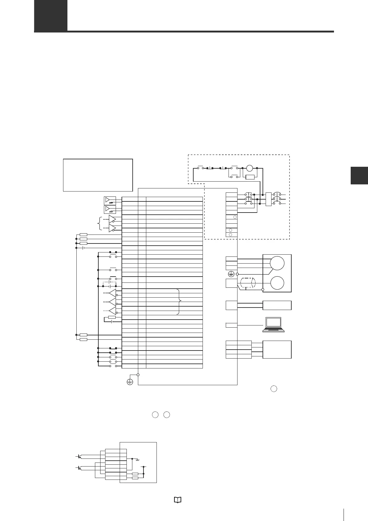
■ Pin assignment and wiring
In position control mode, the following wiring diagram can be used.
Wiring is different when using power supplies of AC 100V,
single-phase AC 200V and DC200V. Please see "Wiring the
Main Circuit/Control Circuit and Motor Power Supply
Connector", page 4-7.
*1 When an external regenerative resistor is used, the same is connected between B1/ -B2. SV-075P2/100P2/
150P2/200P2/300P2/500P2 has a built-in regenerative resistor. B2 and B3 are short-circuited. The wire
between B2 and B3 should be disconnected before the external regenerative resistor is connected.
*2 These are short-circuited when delivered. No polarity needs to be considered when connecting a DC reactor.
*3 The AC100V type has no the L3/ 1/ 2 terminals.
*4
The differential line driver is AM26C31 or similar.
*5 The wiring diagram when
the differential line driver is AM26C31 or similar. The wiring diagram for open collector
input is as follows.
*6 SG (signal ground) is short-circuited internally.
For wiring and specification of I/O terminal, see "4-5 Wiring I/O Signals", Page 4-24.
NFB No fuse breakeer
NFB No fuse breakeer
SA Surge absorber (surge killer)
M Motor
ENC Encoder
RA Alarm output relay
FIL Noise filter
COM1
INPOS
TLM
SG
ALARM
COM0
A+
NP+
SVON
NP
-
ˉ
PP
-
ˉ
FSTOP
V-REF
SG
T-REF
A
-
Z+
B
-
PP+
SEN
ZSP
ˉ
RDY
B+
NTL
ZOC
SG
Z
-
RESET
PTL
LSN
LSP
PL2
PL1
CLR
ˉ
I/O connector
Analog torque limit/Torque feed forward
Signal ground *6
Speed feed forward
Positive pulse input -
Positive pulse input +
Negative pulse input -
Negative pulse input +
Signal ground *6
Operation ready
Encoder pulse Z phase +
Unused
Absolute position data re
quest
Servo ON
Encoder pulse B phase -
Encoder pulse Z phase -
Limit switch negative
Alarm reset
Zero speed detection
Unused
Limit switch positive
Output common
In position
Encoder pulse Z phase open collector
Signal ground *6
Encoder pulse A phase +
Negative torque limit selection
Unused
Encoder pulse A phase -
Encoder pulse B phase +
Alarm
Unused
Deviation clear
Forced stop
Limiting torque
Positive torque limit selection
Power supply for open collector command *5
Power supply for open collector command *5
Input common
RA
*5
NFB
Servo motor
*1
Emergency
stop
MC
SA
*2
MC
Analog
monitor
connector
ǂProtective ground terminal
AC 200V type servo amplifier
T
FIL
R
S
Main circuit/
controlcircuit
power supply
connector
*3
Lithium battery with battery housing
+
-
Battery
connector
TMON
SG
2
4
PC
USB
connector
Measuring instrument
VTG
SG
1
3
V
W
Encoder
connector
Motor power
supply
connector
U
M
ENC
MC
Main
circuit
ON
3
4
5
6
7
8
10
11
14
15
16
17
18
19
20
21
22
23
*4
Main
circuit
OFF
RA
B2
B3
L2
L1C
L3
L2C
L1
B1/
+
-
1
-
2
26
27
28
29
30
31
32
33
34
35
38
39
41
42
43
44
45
46
24
25
24V
24V
24V
NP+
SG
7
8
9
10
11
12
34
35
SG
PL1
NP
-
PP
-
PP+
PL2
12V
Servo amplifier
 Loading...