4-7
4-3 Wiring the Power Supply of Main/Control Circuit
SIGNALS AND WIRING
- SV Series User’s Manual -
Wiring the Main Circuit/Control Circuit and Motor Power Supply Connector
The main circuit/control circuit and motor power supply connector consists of main circuit power supply terminals and
control power supply terminals.
For servo amplifiers above 2kW, the main circuit power terminal, control circuit power terminal and motor connection
terminal of are screw terminals. Be sure to tighten firmly according to the tightening torque of 1.2-1.4Nm (1.8Nm for
5kW motor connection terminal).
Follow these instructions when wiring the main circuit/control circuit and motor power
supply connector of the servo amplifier.
• Do not turn on the servo amplifier until wiring is completed, including the main circuit/
control circuit and motor power supply connector.
• Remove the main circuit/control circuit and motor power supply connector from the
servo amplifier to connect wiring.
• Insert one wire into each of the wire insertion ports of the main circuit/control circuit and
motor power supply connector.
•
When inserting a wire, be careful that the frayed core wire does not touch (short-circuit) nearby wires.
• For servo amplifiers above 2kW, be sure to tighten all the screw terminals (including the
terminals not connected) according to the specified tightening torque.
■ Wiring procedure
1 Remove the main circuit/control circuit and motor power supply connector from the servo amplifier.
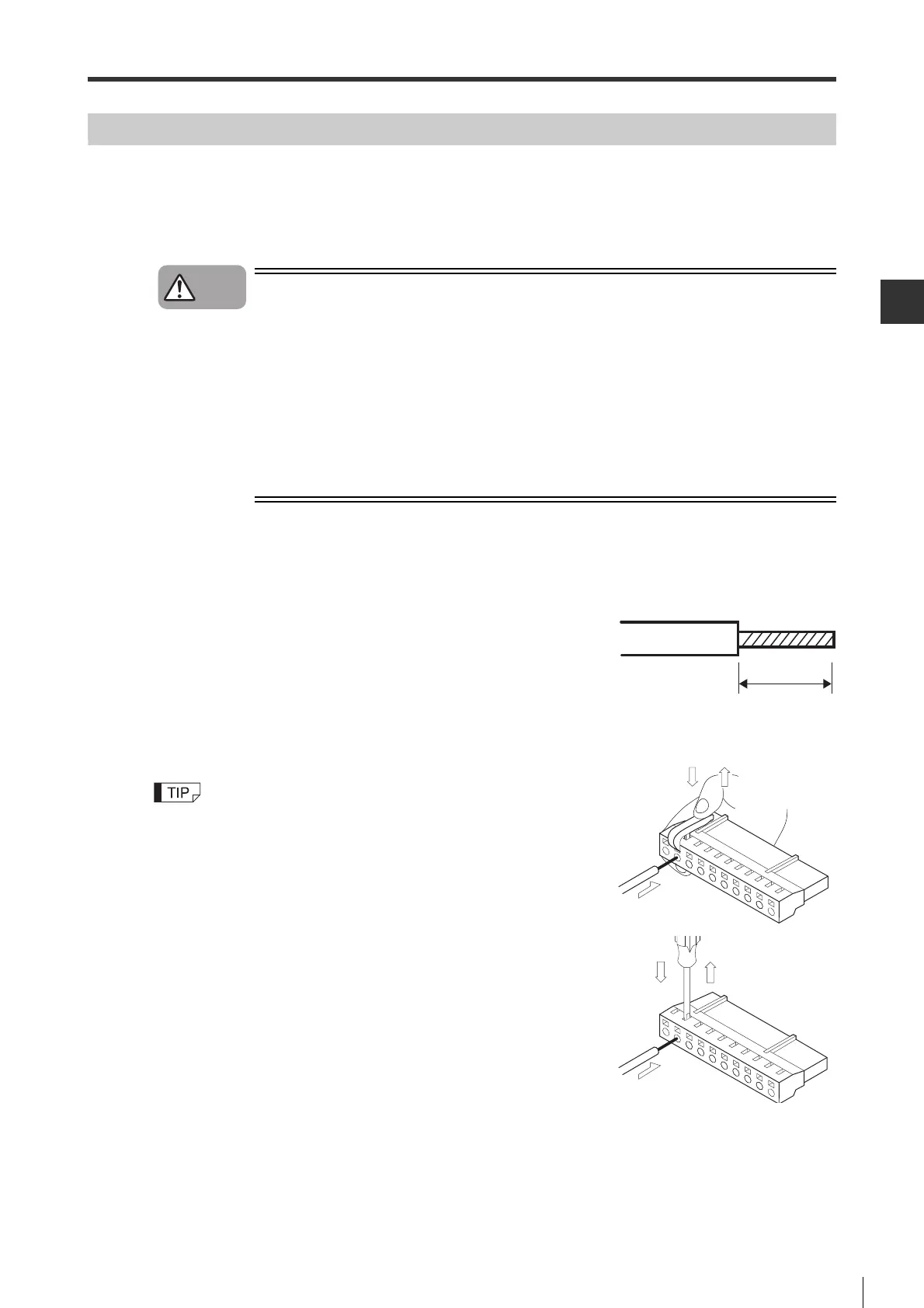
2 Strip the end of the wire used for connection.
3 Use a tool to open the wire insertion port of the power supply connector.
To open the port, use one of the following two methods:
• To use a spring opener supplied with the servo amplifier:
A spring opener from Tyco Electronics AMP (1981045-1) can also be used.
• To use a commercially available flathead screwdriver:
Insert a commercially available flathead screwdriver (tip width: 3.0 to 3.5 mm)
into the port and open it.
* Do not insert too far. Otherwise, this may cause damage to the connector.
4 Insert the core wire into the wire insertion port.
After the core wire is inserted, pull out the connector lever or screwdriver and confirm that the wire is securely connected.
5 Repeat the steps above to connect all necessary wires.
6 Connect to the servo amplifier.
Caution
8 to 9mm
 Loading...