A-38
- SV Series User’s Manual -
APPENDIX
A-5
MECHATROLINK-II Communication Commands
Overview
Overview of MECHATROLINK-II communication commands
In addition to the methods mentioned in Chapter 6, SV series can also use MECHATROLINK-II communication
commands to send operation commands to servo motor.
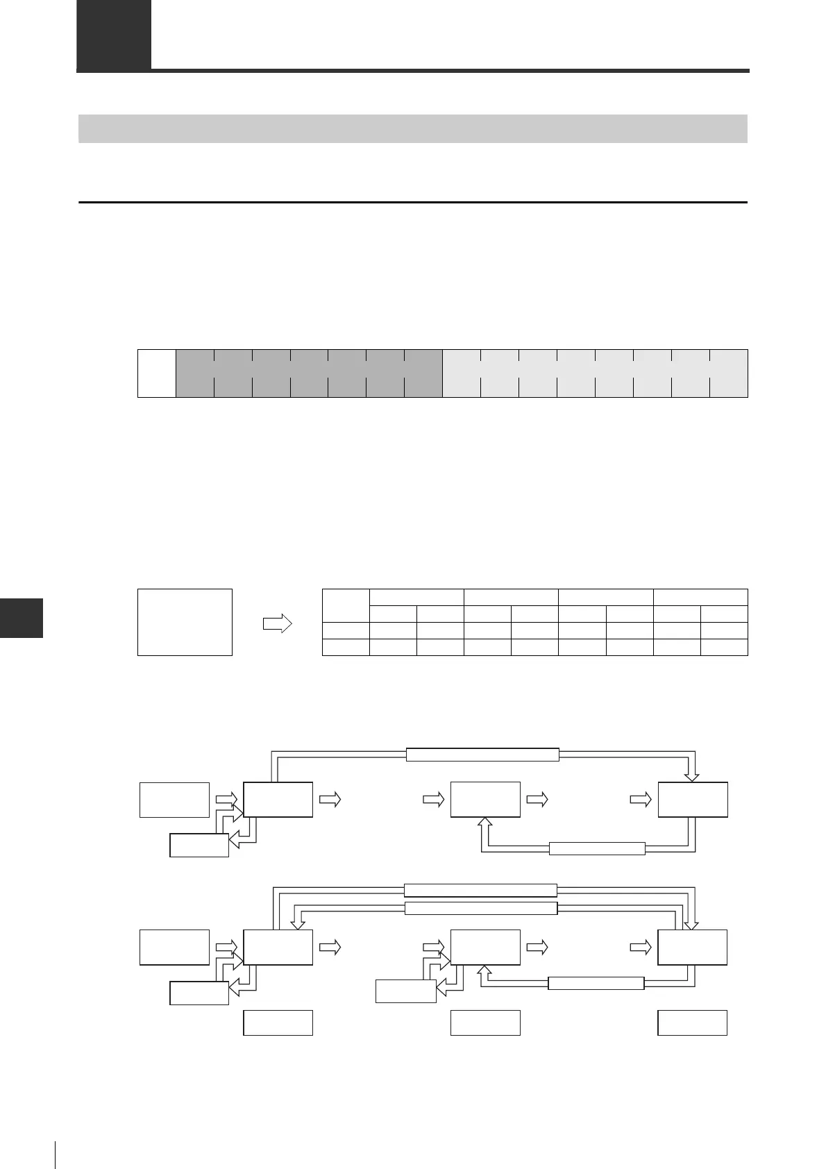
■Frame structure
The command frame structure is as follows:
0 : always "03H". "01H" is add automatically in a response.
1 to 16 : Used in main command. The set value varies depending on the command used. So please see command
list for details.
17 to 29 : Used in sub command. The combination of main command and sub command is limited.
30 to 31 : Not used.
■Data entry format
Data for response frame are reverse input (lower byte sequence) in MECHATROLINK-II communication.
■Communication sequence for master/slave station
The status of master/slave station will change as follows in master/slave station communication.
012
···
16 17
···
29 30 31
Contro
l
sectio
Primary command area Secondary command area
Data received Data entered
1234ABCD
1st byte 2nd byte 3rd byte 4th byte
High bit Low bit High bit Low bit High bit Low bit High bit Low bit
ASCII C D A B 3 4 1 2
HEX 43H 44H 41H 42H 33H 34H 31H 32H
ֵফTCENNOC
Communication sequence for master station
When powering
ON
When powering
ON
Communication sequence for slave station
Communication
abnormal
Communication
abnormal
Phase 1
CONNECT publish
(non-sync
communication)
CONNECT publish
(non-sync
communication)
Connection
establishment
wait
Connection
confirmation
wait
CONNECT (sync communication) publish
Non-sync
communication
status
Non-sync
communication
status
CONNECT receive
DISCONNECT receive
Communication
abnormal
Phase 2 Phase 3
Communication abnormal
Communication abnormal
SYNC_SET publish
(sync communication)
SYNC_SET publish
(sync communication)
Sync
communication
status
Sync
communication
status
 Loading...