4-4
SIGNALS AND WIRING
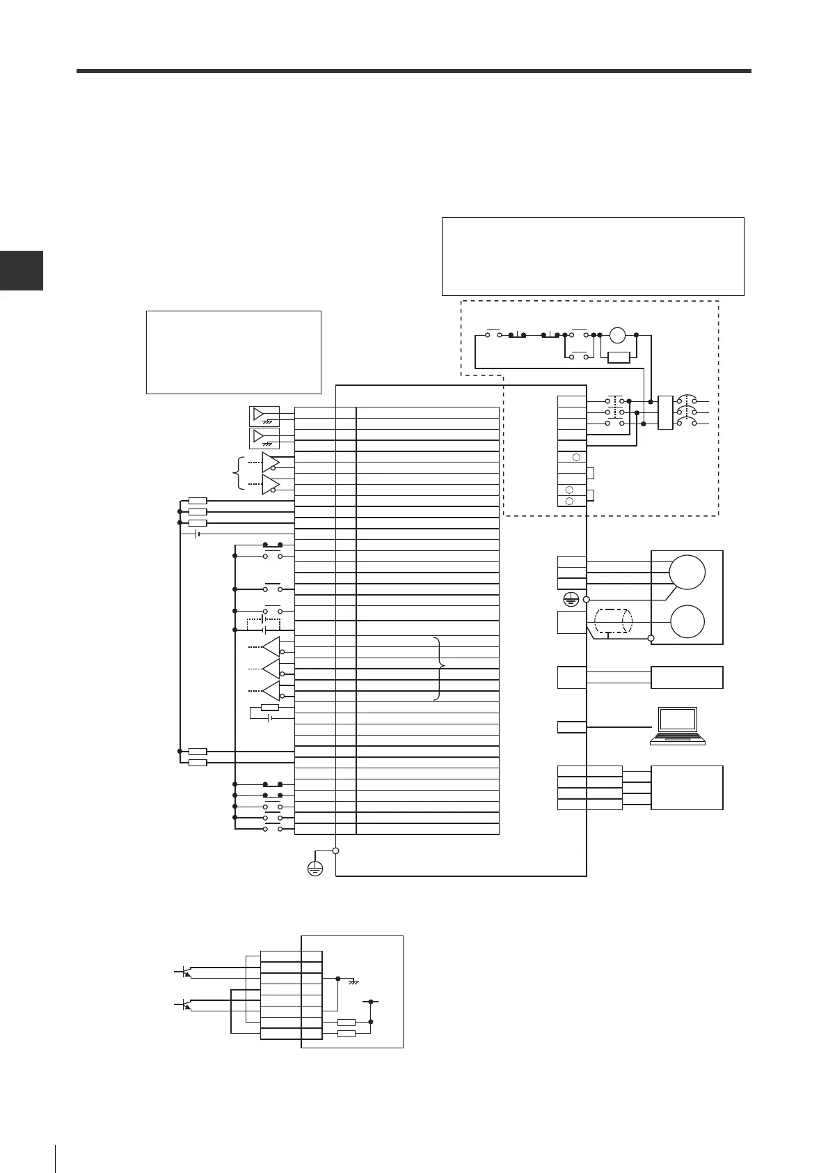
4-2 Standard Wiring Diagram
- SV Series User’s Manual -
■ Standard wiring diagram for pulse/analog input type
When performing position control, speed control, torque control of pulse/analog input type servo amplifier, terminals
used are different from each other. Please refer to the following wiring diagram for wiring.
● Position control(When 3-phase AC200V power supply is used)
*1 Differential line driver equivalent to AM26C31.
*2 This wiring diagram is for the input of differential line driver equivalent to AM26C31. The wiring diagram for
opencollector input is as follows:
*3 SG (signal ground) is short-circuited internally.
*4 The alarm will output for max. 5s when powering on the control loop.
*5 Wiring is different depending on whether to use an external regenerative resistor or a DC reactor.
NFB No fuse breakeer
MC Magnetic contactor
SA Surge absorber (surge killer)
M Motor
ENC Encoder
RA Alarm output relay
FIL Noise filter
COM1
INPOS
TLM
SG
ALARM
COM0
A+
NP+
SVON
NP
-
-
PP
-
-
FSTOP
V-REF
SG
T-REF
A
-
Z+
B
-
PP+
SEN
ZSP
-
RDY
B+
NTL
ZOC
SG
Z
-
RESET
PTL
LSN
LSP
PL2
PL1
CLR
-
I/O connector
Analog torque limit/Torque feed forward
Signal ground *6
Speed feed forward
Positive pulse input -
Positive pulse input +
Negative pulse input -
Negative pulse input +
Signal ground *6
Operation ready
Encoder pulse Z phase +
Unused
Absolute position data re
quest
Servo ON
Encoder pulse B phase -
Encoder pulse Z phase -
Limit switch negative
Alarm reset
Zero speed detection
Unused
Limit switch positive
Output common
In position
Encoder pulse Z phase open collector
Signal ground *6
Encoder pulse A phase +
Negative torque limit selection
Unused
Encoder pulse A phase -
Encoder pulse B phase +
Alarm
Unused
Deviation clear
Forced stop
Limiting torque
Positive torque limit selection
Power supply for open collector command *5
Power supply for open collector command *5
Input common
RA
*5
NFB
Servo motor
*1
Emergency
stop
MC
SA
*2
MC
Analog
monitor
connector
Protective ground terminal
AC 200V type servo amplifier
T
FIL
R
S
Main circuit/
controlcircuit
power supply
connector
*3
Lithium battery with battery housing
+
-
Battery
connector
TMON
SG
2
4
PC
USB
connector
Measuring instrument
VTG
SG
1
3
V
W
Encoder
connector
Motor power
supply
connector
U
M
ENC
MC
Main
circuit
ON
3
4
5
6
7
8
10
11
14
15
16
17
18
19
20
21
22
23
*4
Main
circuit
OFF
RA
B2
B3
L2
L1C
L3
L2C
L1
B1/
+
-
1
-
2
26
27
28
29
30
31
32
33
34
35
38
39
41
42
43
44
45
46
24
25
24V
24V
24V
Wiring is different when using power supplies of AC
100V, single-phase AC 200V and DC200V. Please see
"Wiring the Main Circuit/Control Circuit and Motor Power
Supply Connector", Page 4-7.
NP+
SG
7
8
9
10
11
12
34
35
SG
PL1
NP
-
PP
-
PP+
PL2
12V
Servo amplifier
 Loading...