5-19
5-3 I/O Signal Setting
COMMON PARAMETER SETTING
- SV Series User’s Manual -
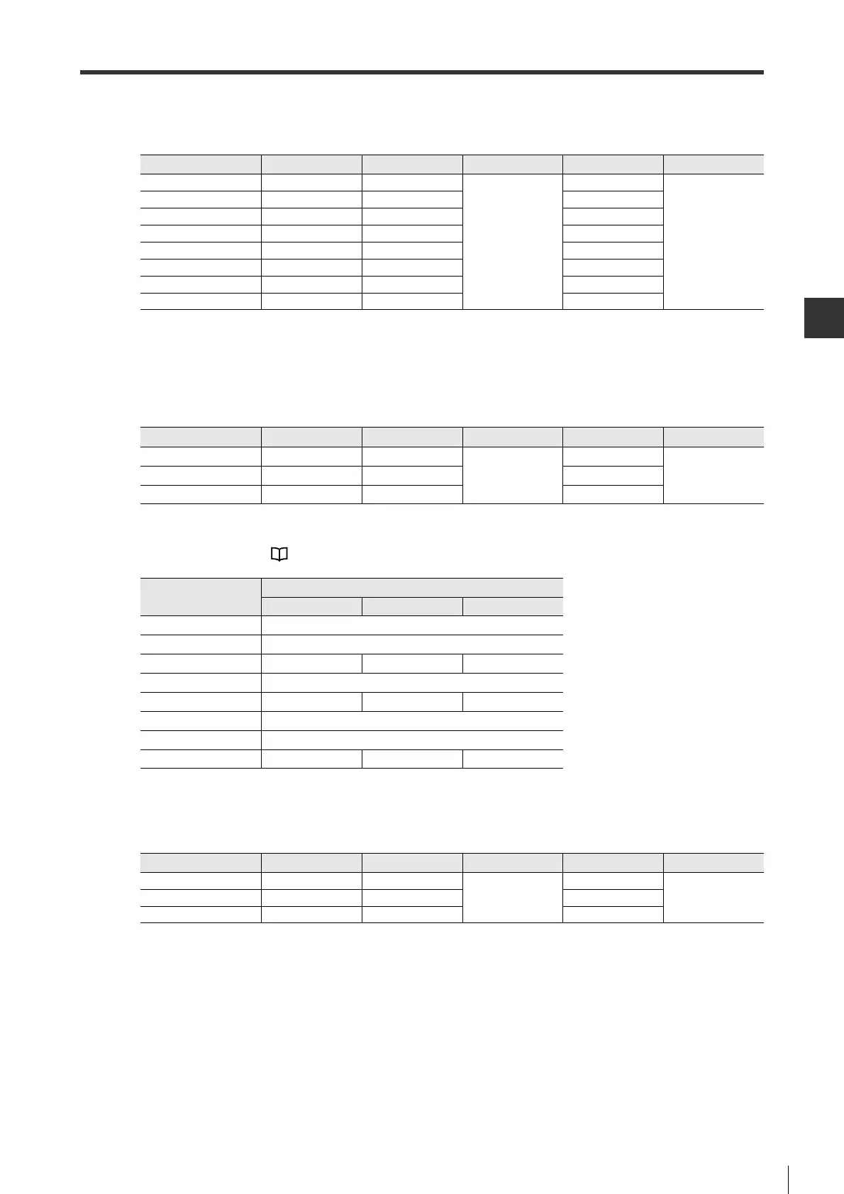
● Polarity setting
Polarity of N.O./N.C. of the assigned signals can be changed. Polarity can be set through a parameter.
■ Output signal
● Signal assignment
The following output signals can be assigned to pin No. 1/23/25. Signal assignment can be set through a parameter.
The output signals that can be set and corresponding set value are shown below.
For output signals, see "4-5 Wiring I/O Signals", Page 4-24.
● Polarity setting
Polarity of N.O./N.C. of the assigned signals can be changed. Polarity can be set through a parameter.
Signal name Pin No. Parameter type Setting range Default Enable timing
FSTOP 2 IO_44
0: N.O.
1: N.C.
1
After power is ON
again
IN1 7 IO_45 1
IN2 8 IO_46 1
IN3 9 IO_47 0
IN4 10 IO_48 0
IN5 11 IO_49 0
IN6 12 IO_50 1
IN7 13 IO_51 0
Signal name Pin No. Parameter type Setting range Default Enable timing
OUT1 1 IO_52
0 to 7
3
After power is ON
again
OUT2 23 IO_53 1
OUT3 25 IO_54 5
Set value
Assigned function
Position control
Speed control Torque control
0 -
1 RDY
2 INPOS VCMP -
3 BRAKE
4 TLM TLM VLM
5 WARN
6 ZSP
7 NEAR - -
Signal name Pin No. Parameter type Setting range Default Enable timing
OUT1 1 IO_55
0: N.O.
1: N.C.
0
After power is ON
again
OUT2 23 IO_56 0
OUT3 25 IO_57 0
 Loading...