4-9
4-3 Wiring the Power Supply of Main/Control Circuit
SIGNALS AND WIRING
- SV Series User’s Manual -
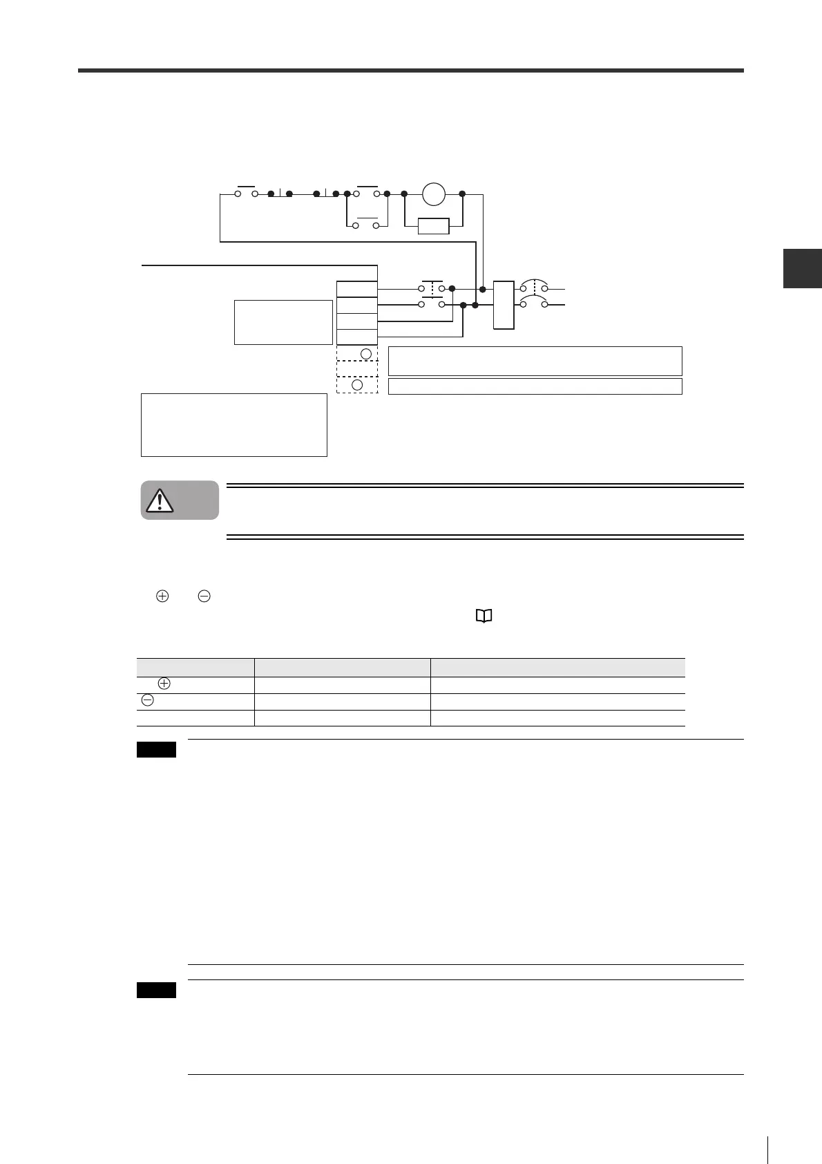
■ 1-phase AC100V (when SV-1 is used)
Wiring example is as follows.
If you wiring the terminals marked with "Not used", the servo amplifier may be damaged.
■ DC power supply (when SV-2 is used)
B1/ and 2 terminals become the input terminals of DC power supply when DC power supply is used.
For the parameter setting when DC power supply is used, see "5-1 Main Circuit/Control Circuit Power Supply
Setting", page 5-2.
• Be sure to connect fuses for DC power input.
• In DC power input mode, "Main circuit wiring error" alarm (330) will occur when AC power is input
from L1, L2 or L3 terminals.
• When DC power is used for SV series, discharging will consume a lot of time after powering
main circuit power OFF. In this case, there is still high voltage inside servo amplifier, take care to
avoid being electrocuted.
• When DC power input is used, because there is no reverse protection circuit inside, do no
connect reversely. Otherwise this may result in failure or damage.
• When AC power supply is used for servo amplifier with built-in regenerative resistor (SV-
075), don't input DC power to main circuit. Otherwise this may result in failure or damage. Be
sure to change the settings under the status that main circuit power is OFF.
• Because regeneration is unavailable for DC power inputs, be sure to apply regeneration
processing at the power supply side.
• DC input cannot be used for 100V type servo amplifier.
• DC power cannot be input to control circuit power terminal.
NFB : No fuse breaker
MC : Magnetic contactor
FIL : Noise filter
SA : Absorber(surge killer)
RA : Alarm output relay
Emergency
stop
Main circuit
ON
Main
circuit
OFF
RA
Main circuit/control
circuit power supply
connector
Servo amplifier (SV-ƶƶƶƶ1)
NFB
FIL
MC
SA
R
SL2
L1C
L2C
MC
L1
MC
B1/ +
B2
ˉ
Do not use an external regenerative resistor
㨯㨯㨯㨯㨯㨯㨯
Do not make wiring.
Be sure to use an external regenerative resistor
㨯㨯㨯㨯㨯
Be sure to connect a regenerative resistor.
Do not make wiring.
Terminal Name Functions and ratings
B1/ Positive terminal of main circuit DC270 to 320V
2 Negative terminal of main circuit DC0V
L1C, L2C Power terminal of control circuit 1-phase, AC200 to 230V, +10 to
-
15%, 50/60Hz
 Loading...