4-28
SIGNALS AND WIRING
4-5 Wiring I/O Signals
- SV Series User’s Manual -
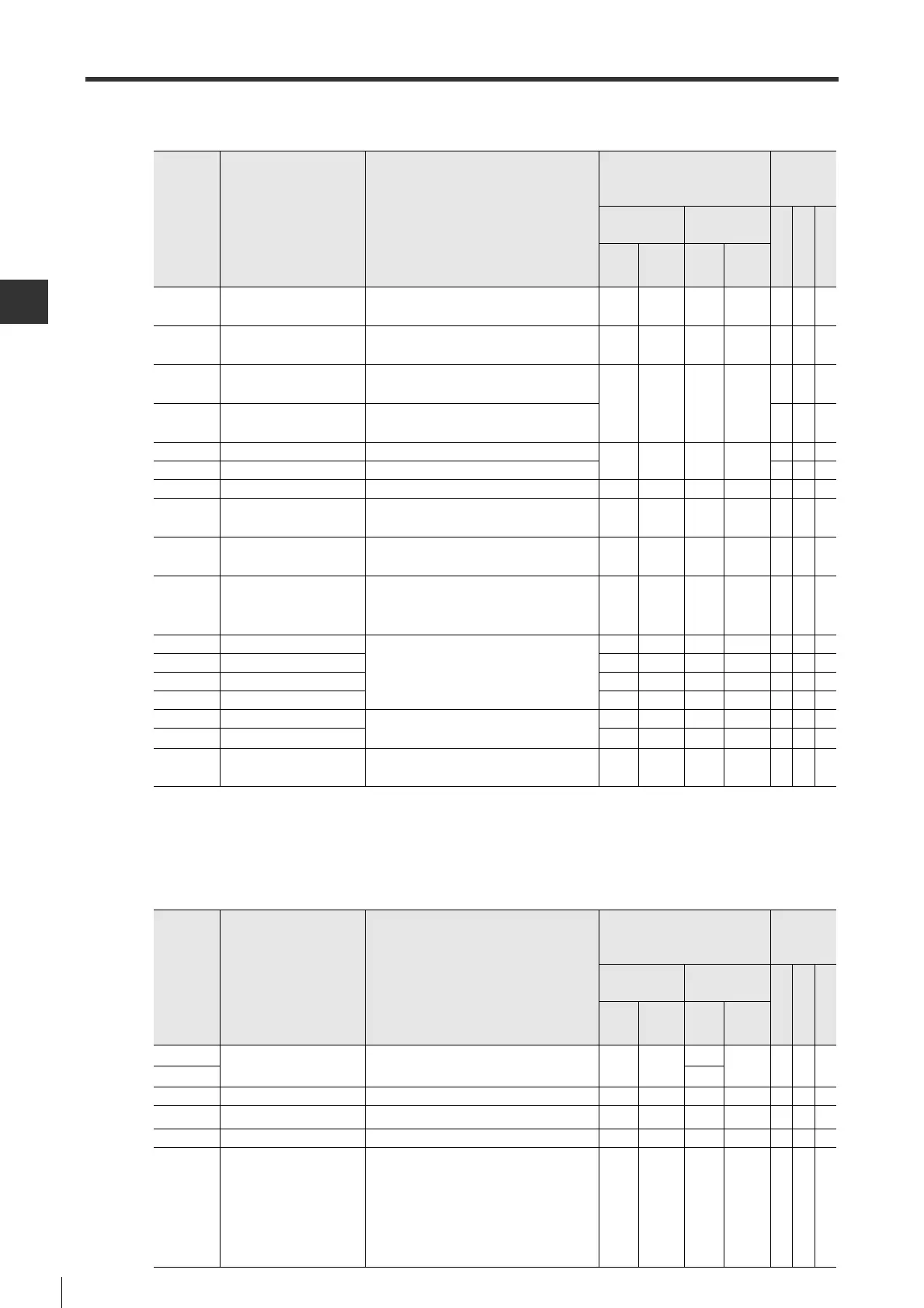
■ Output terminals
■ Power terminals
Terminal Description Function Description
Connector pin No.
and reference circuit
diagram
Supported
control
mode
MECHATROLINK-II
type
Pulse/analog
input type
Position
Speed
Torque
Termi
nal
Circuit
Termi
nal
Circuit
ALARM Alarm
OFF when internal servo amplifier alarm
occurs.
*2
3DO-114DO-1
○○○
WARN Warning
ON when internal servo amplifier warning
occurs.
25 DO-1 -
*1
*1 The terminal can be used with I/O signal assignment.
*2 Alarm can be output up to 5 seconds when control circuit is powered ON.
-
○○○
INPOS Inposition
ON when the absolute value of position
deviation is within "INPOS range" (POS_04).
-
*1
-16DO-1
○
--
VCMP Speed match
ON when feedback speed is within
"Speed match range" (VEL_04).
-
○
-
TLM Torque limit in progress
ON during torque limit process.
-
*1
-15DO-1
○○
-
VLM Speed limit in progress
ON during speed limit process.
--
○
RDY
Operation ready complete
ON when operation is ready after inputting servo ON signals.
23 DO-1 38 DO-1
○○○
ZSP Zero speed detection
ON when feedback speed of motor is less than "Zero
speed detection range" (VEL_15).
-
*1
-39DO-1
○○○
NEAR Positioning approaching
ON when the absolute value of position deviation
is within "NEAR range" (POS_11).
-
*1
--
*1
-
○
--
BRAKE
Electromagnetic brake
timing
To control the electromagnetic brake of a
motor when motor with electromagnetic
brake is used.
1DO-1-
*1
-
○○○
A+
Encoder pulse A-phase +
To output the pulse set through "Encoder
output pulse" (SYS_03) in differential line
driver mode.
17 DO-E 26 DO-E
○○○
A
-
Encoder pulse A-phase -
18 DO-E 27 DO-E
○○○
B+
Encoder pulse Z-phase +
19 DO-E 28 DO-E
○○○
B
-
Encoder pulse B-phase -
20 DO-E 29 DO-E
○○○
Z+
Encoder pulse Z-phase +
To output the Z-phase of encoder output
pulse in differential line driver mode.
21 DO-E 30 DO-E
○○○
Z
-
Encoder pulse Z-phase -
22 DO-E 31 DO-E
○○○
ZOC
Open collector of
encoder pulse Z-phase
To output the Z-phase of encoder output
pulse in open collector mode.
24 DO-2 32 DO-2
○○○
Terminal Description Function Description
Connector pin No.
and reference circuit
diagram
Supported
control
mode
MECHATROLINK-II
type
Pulse/analog
input type
Position
Speed
Torque
Termi
nal
Circuit
Termi
nal
Circuit
PL1
Power supply for
open collector command
Used when input position command via
open collector signal.
--
34
-
○
--
PL2 35
COM0 Input common common terminal for input terminals. - - 25 -
○○○
COM1 Output common common terminal for output terminals. 26
-
17 -
○○○
COM0+
Input common (+24V)
common terminal for input terminals. 6 - - -
○○○
SG Signal ground Signal ground inside servo amplifier. 16
-
1
4
6
9
12
33
-
○○○
 Loading...