4 Transport, installation and commissioning
Commissioning
MB-20-G/MB-200G-W_MB-LABmaster_MB-200 MOD_TP700
Operating Manual - V5.0 - 04/2018 - STD
Page
4 - 33
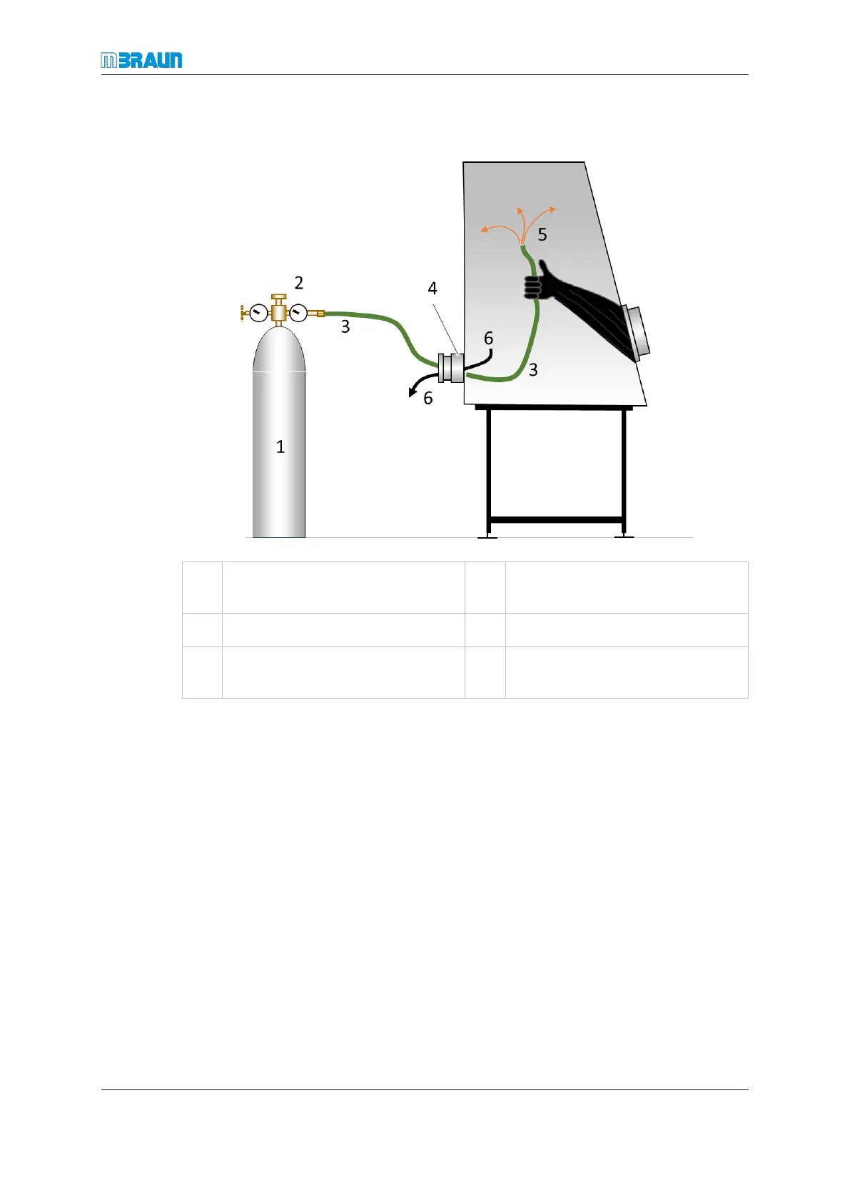
Performing a manual purge
1 Purge gas source 2 Pressure reducing valve, 3.0 bar
(0.3 MPa)
3 Reinforced hose 4 Open flange
5 Inert gas exhaust into the glovebox 6 Mixed ambient air and inert gas es-
cape
► In a two-glovebox system, each glovebox must be purged separately. Both boxes
must have an open connection to the circulation pipework.
► Open freezers or equipment with areas that may be protected by covers.
► Set up purge gas source (working gas) with pressure reducing valve.
► Connect reinforced hose to purge gas source.
► Open one KF40 “blind flange” on glovebox.
► Feed one end of the reinforced hose through the open flange into the gloves.
► Set the pressure-reducing valve on the purge gas source to 3.0 bar (0.3 MPa) and
open the valve.
ð Air and purge gas escapes through the flange opening.
► Pick up the reinforced hose with a glove, and purge the glovebox interior from top to
bottom using a circular motion.
► Carefully purge corners, edges and box fittings.
The purge time should be about 45 min per 1m
3
of glovebox volume to achieve an appro-
priate gas displacement with an oxygen concentration of less than 100 ppm (V).