4 Transport, installation and commissioning
Installation
MB-20-G/MB-200G-W_MB-LABmaster_MB-200 MOD_TP700
Operating Manual - V5.0 - 04/2018 - STD
Page
4 - 23
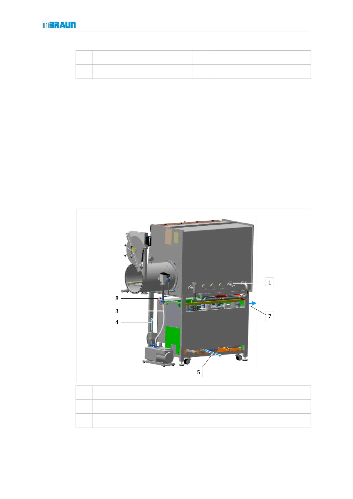
5 Regeneration gas outlet 6 Gas outlet glovebox
7 Purge gas and working gas outlet 8 Vacuum connection of gas purifier
► Install Ø 40 pipework according to the figure above.
► Connect operating company-specific feedthroughs (1).
► Connect gas outlet pipe of the gas purifier to gas inlet pipe of the glovebox (2).
► Connect vacuum hose to the antechamber with gas inlet of the vacuum pump (3).
► Connect gas exhaust of vacuum pump to disposal equipment on operating com-
pany’s premises (4).
► Connect regeneration gas outlet (NOTE: with condensate) to disposal equipment on
operating company’s premises (5) (optionally a condensing device is available).
► Connect gas inlet pipe of the gas purifier to gas outlet of the glovebox (6).
► Connect exhaust to disposal equipment of operating company’s premises(7).
► Connect the vacuum hose from the antechamber to the vacuum connection of gas
purifier (8).
Installation of a workstation LABmaster
1 Feedthrough 3 Vacuum pump
4 Vacuum pump exhaust 5 Regeneration gas outlet
7 Purge gas exhaust 8 Vacuum connector of gas purifier
► Install Ø 40 circulation pipework as shown in the figure above.