4 Transport, installation and commissioning
Installation
MB-20-G/MB-200G-W_MB-LABmaster_MB-200 MOD_TP700
Operating Manual - V5.0 - 04/2018 - STD
Page
4 - 25
Workstation LABmaster sp/dp
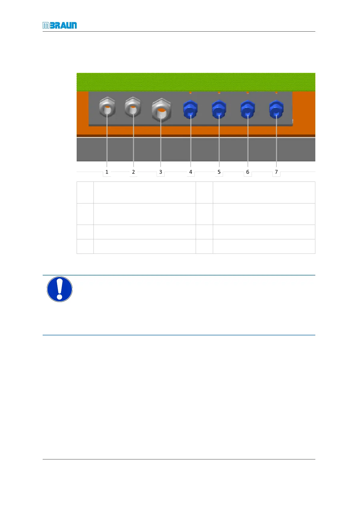
The media connection points are located at the bottom of the rear side of the workstation.
1 Cooling water inlet 2 Electrical connection to vacuum
pump
3 Regeneration gas outlet (condens-
ate)
4 Regeneration gas inlet
5 Working gas inlet 6 Cooling water inlet
7 Cooling water outlet
Connecting the gas supply and exhaust lines
NOTICE
Media pressure too high
Property damage through exploding piping
► Before connecting a media line, always check that the pressure in the supply pipe at
the connection point is not higher as the allowed connection pressure.
► Check the set value on your pressure regulation valve.
Connecting the cooling water
Not applicable for systems with no cooling or which are equipped with compressor cool-
ing.
Systems with components that require specific cooling may have an individual cooling
supply, which is distributed from a water supply or from a cooling unit.
► Connect the cooling water inlet system connection to the cooling water source.
► Connect the cooling water outlet system connection to the depressurised water dis-
posal. Return pressure is max. 0.5 bar (50 kPa).
► Switch on the cooling water. The cooling water flow rate setting depends on the
available water flow rate.