Rise Time to 90% of Level: <10ns
Programmable Pulse Width: 100ns to 900ms with 20ns resolution
Absolute Phase Error: ±50ns (1σ)
Programmable Phase Shift: ±5ns to 500ms with 5ns resolution
1PPS Input and Output: Viewing Signal State
To quickly view if the PPS inputs and outputs of this option card are currently
enabled or disabled, go to the option card’s Status Summary panel. For instruc-
tions, see: "Viewing an Input/Output Signal State" on page366.
1PPS Input: Edit Window
To configure the settings for the 1PPS Input (also referred to as ‘Reference’), go
to its Edit window. For instructions, see: "Configuring Option Card Input-
s/Outputs" on page364.
The Web UI list entries for these cards are: 1PPS/Frequency BNC and 1PPS/Fre-
quency RS- 485. The connector number is: J2 (Model 1204- 03: RS- 485 con-
nector: Pins 5 and 6)
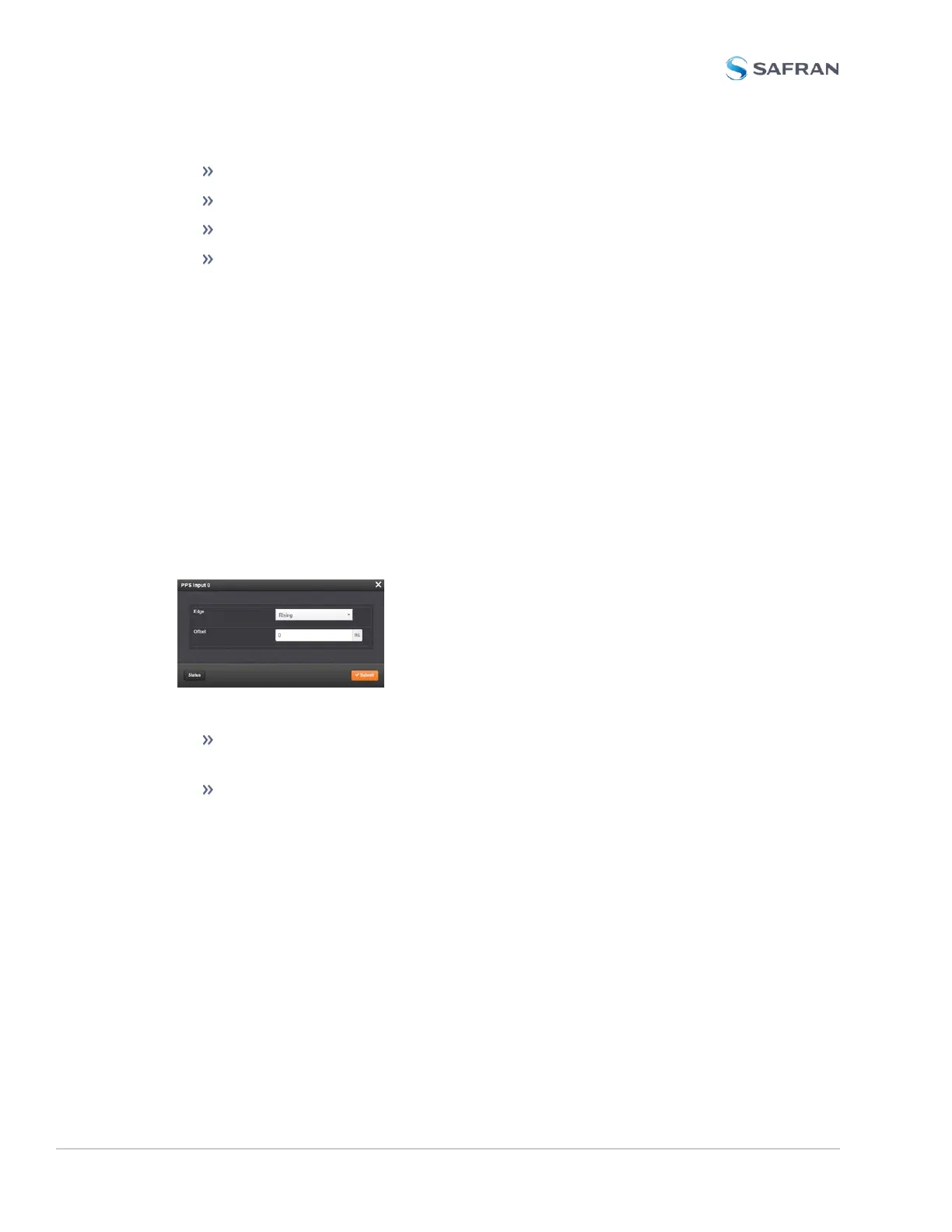
The Edit window allows the configuration of the following settings:
Edge: The operator can select either the rising or the falling edge as the
input time reference (defines the on-time point of the signal).
Offset: It is possible to add an offset to the input signal (to account for
cable delays), with a resolution of 5ns and a positive or negative value of
500ms maximum.
1PPS Input: Status Window
To view the current settings of the PPS Input (also referred to as ‘Reference’), go
to its Status window. For instructions, see: "Verifying the Validity of an Input Sig-
nal" on page367.
398 SecureSync 2400 User Manual
APPENDIX