The Web UI list entries for these cards are: 1PPS/Frequency BNC and 1PPS/Fre-
quency RS-485. The connector number is: J2 (Model 1204-03: RS-485 connector:
Pins 5 and 6)
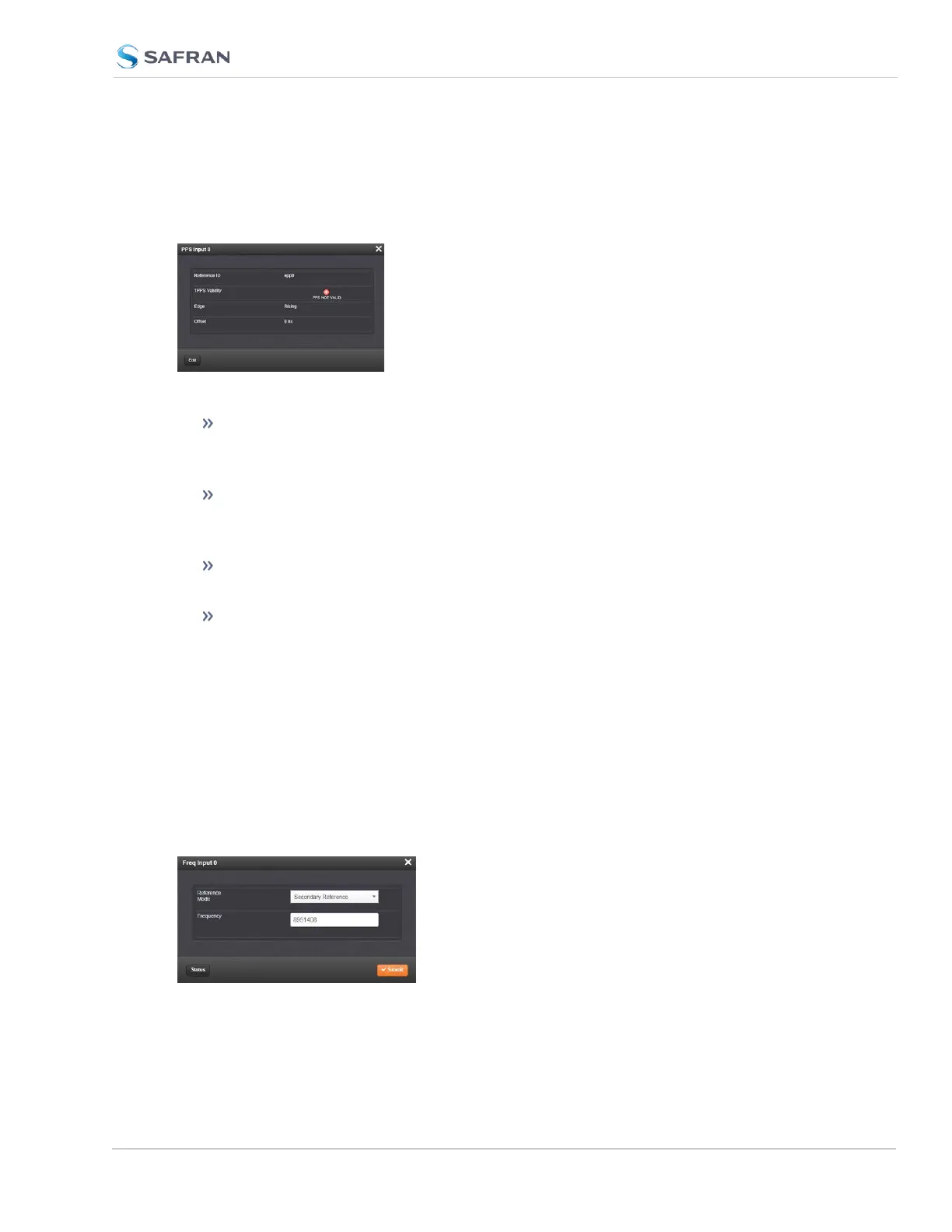
The Status window displays the following settings:
Reference ID: Name used to represent this 1PPS input reference in the
Reference Priority table; see "Configuring Input Reference Priorities" on
page205 for more information on reference priority configuration.
1PPS Validity: Indicates “OK” (green) if the 1PPS input signal is present and
valid. Indicates “Not Valid” (orange) if the 1PPS input signal is either not
present or is not considered valid.
Edge: Displays the selected Edge (rising of falling) of the 1PPS input that
defines the on-time point.
Offset: Displays the configured 1PPS offset values.
The 1PPS Input signal is analyzed and an absence of the signal triggers a “Not
Valid” indication.
Frequency Input: Edit Window
To configure the settings for the Frequency Input (also referred to as ‘Refer-
ence’), go to its Edit window. For instructions, see: "Configuring Option Card
Inputs/Outputs" on page364.
The Web UI list entries for these cards are: 1PPS/Frequency BNC and 1PPS/Fre-
quency RS-485. The connector number is: J1 (BNC card); J1 (RS-485 card).
SecureSync 2400 User Manual 399
APPENDIX