PIN NOTES SIGNAL
819x Map-
ping
819x Option17 Map-
ping
4 Ground = Normal
OPEN = ALARM
Major
Alarm
Major Alarm Major Alarm
5 Cable Shield Ground Ground Ground
6 RS-485 – Ter-
minal
Output 0 – –9.6 kHz – CTCSS #1
7 RS-485 – Ter-
minal
Output 1 – –18 kHz – 18 kHz
8 RS-485 – Ter-
minal
Output 2 – –1PPS – CTCSS #2
9 Cable Shield GROUND GROUND GROUND
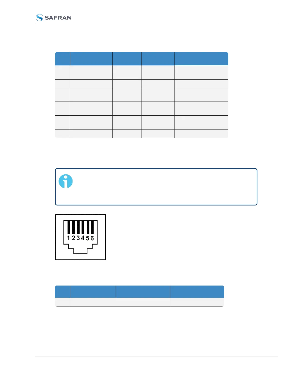
Pin Assignment: RJ-12 Connector
Outputs: Alarm1, Alarm2, CTC3 Out, (with only one Simulcast option card
installed)
Note: Alarm Output 0 through Alarm Output 3 are reserved by
SecureSync. In the Web UI, numbering for alarm outputs for this
option card will begin at Alarm 4, which is available on the DB-9 out-
put, while Alarms 5 and 6 are assigned to the RJ-12 connector.
Figure 5-32: RJ-12 connector pin-out
Table 5-9: RJ-12 pin assignments
PIN NOTES SIGNAL 938x SP360 Mapping
1 Cable Shield GROUND GROUND
SecureSync 2400 User Manual 417
APPENDIX