PIN NOTES SIGNAL 938x SP360 Mapping
2 5V = NORMAL
GROUND = ALARM
MAJOR ALARM RELAY MAJOR ALARM RELAY
3 RS-485 + Terminal Output 3+ + 1PPS
4 RS-485 - Terminal Output 3- - 1PPS
5 5V = NORMAL
GROUND = ALARM
MINOR ALARM RELAY MINOR ALARM RELAY
6 Cable Shield GROUND GROUND
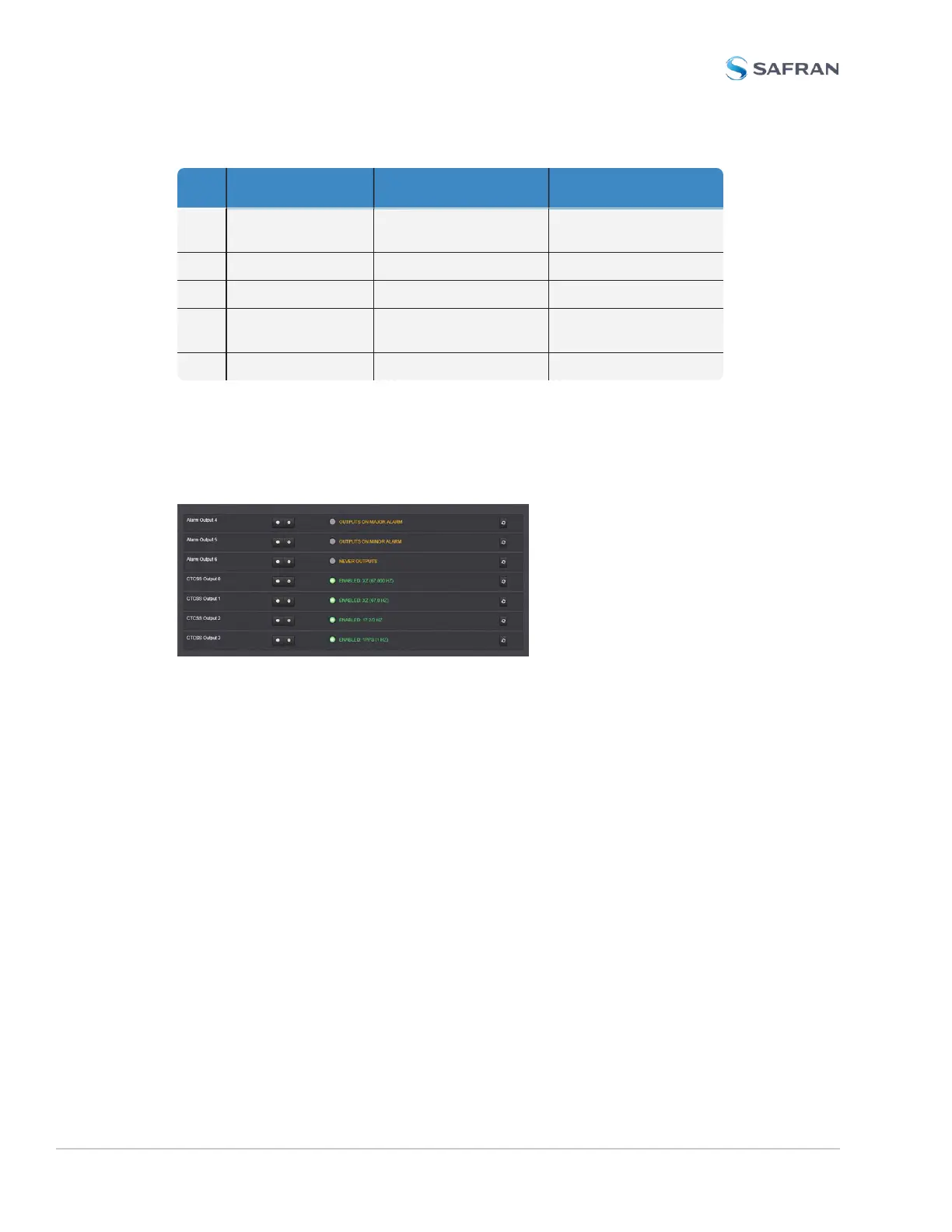
CTCSS and Alarm Outputs: Viewing Signal States
To quickly view the current signal state of the 1204-14 Simulcast outputs, in the
Web UI navigate to the option card’s Status Summary panel. For instructions,
see: "Viewing an Input/Output Signal State" on page366.
All outputs are listed, displaying their current output states. For a listing of the
states, see "CTCSS Outputs: Edit Window" on the facing page, and "Alarm Out-
puts: Edit Window" on page420.
To view the settings of one of the Alarm Outputs or CTCSS Outputs, go to its
Status window. For instructions, see: "Viewing Input/Output Configuration Set-
tings" on page363.
The Web UI list entry for this card is named: Simulcast.
418 SecureSync 2400 User Manual
APPENDIX
 Loading...

