Note: The supplied antenna cable is 2.4m (96") long. Longer
cables are available upon request. The antenna does not
require a separate power supply.
5. Connect the antenna cable to the SecureSync unit via the SMA connector
on the option card -3E rear plate. The SecureSync can be in a powered off
or a powered on state during antenna installation.
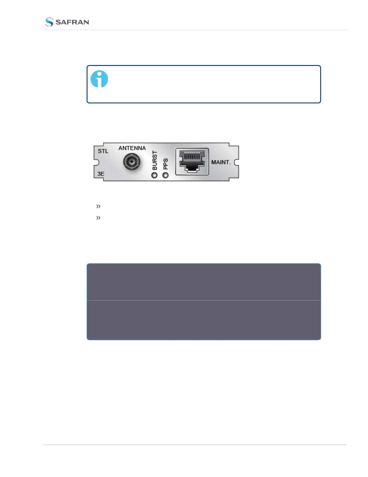
Figure 5-57: Model 1204-3E option card rear plate
If the unit is ON, verify that the BURST lamp is blinking.
If the unit is OFF, turn it on, and wait until the BURST lamp is blinking.
If the BURST lamp is not blinking after the subscription has been activ-
ated, the STL receiver is not receiving an STL signal. Check the antenna
cable and its connections, and the antenna location. Move the antenna to
another location (higher or closer to an outside wall).
R e a r P l a t e L E D s :
BURST: Indicates the incoming STL burst rate. A high burst rate (desired) is
indicated by the LED flashing quickly.
PPS: Indicates that the STLreceiver is sending out a PPS signal to SecureSync.
One (1) pulse per second means that the receiver is locked. NOTE: It can take
approximately 10 minutes or longer until the receiver is locked. This depends on
the burst rate (see "Burst Rate" on page525.)
Both LEDs have equivalent indicators in the Web UI STL 0 status window:
SecureSync 2400 User Manual 519
APPENDIX