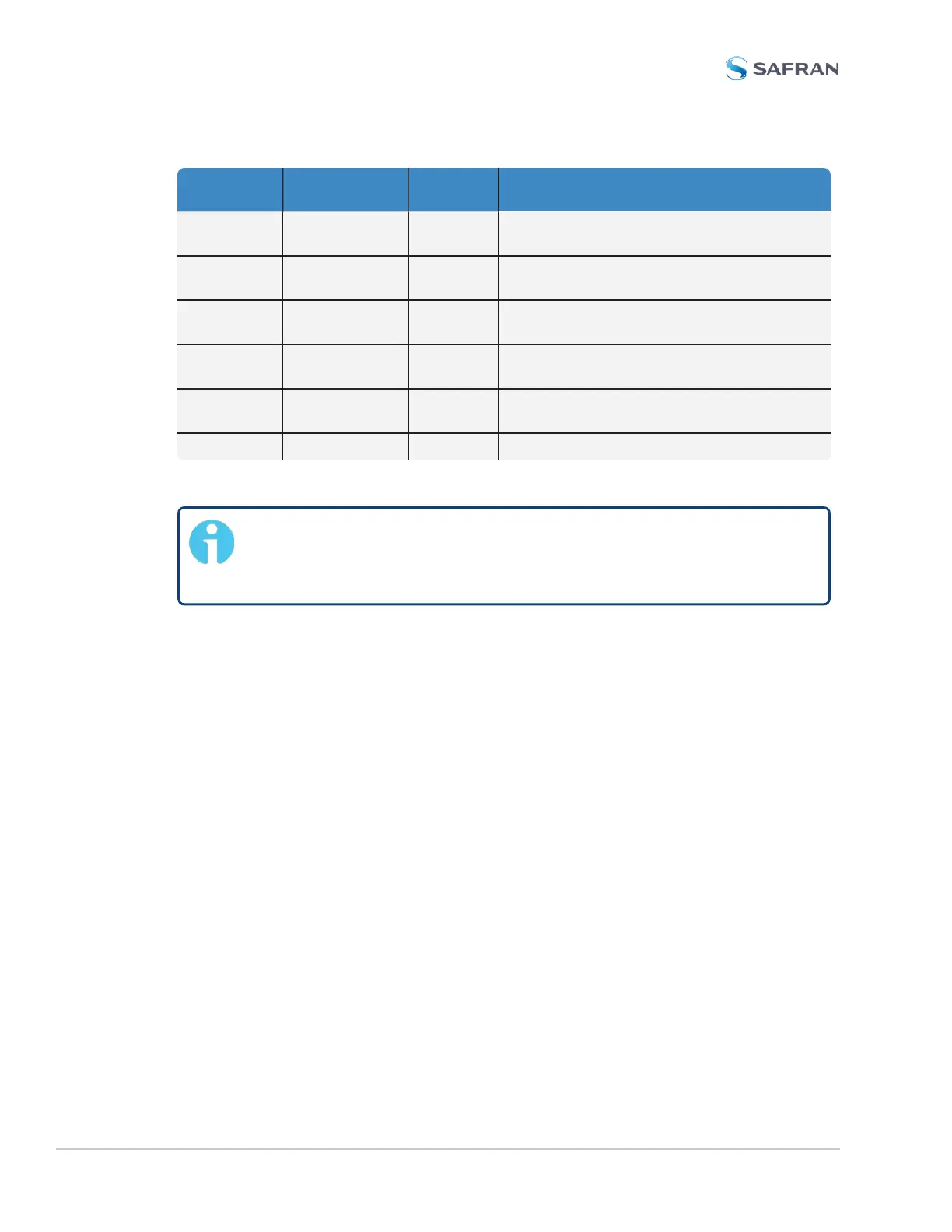
Connector
Pin
Signal Direction Characteristics
5 Relay 1 NC Out Normally Closed 30 V
DC
, 2A max.switching
power
6 Relay 1
COMMON
Out Common Contact 30 V
DC
, 2A max.switching
power
7 Relay 2 NO Out Normally Open 30 V
DC
, 2A max.switching
power
8 Relay 2 NC Out Normally Closed 30 V
DC
, 2A max.switching
power
9 Relay 2
COMMON
Out Common Contact 30 V
DC
, 2A max.switching
power
10 GROUND N/A GROUND
Table 5-28: Relay/RS-485 outputs pin assignments
Note: The last device on each of the RS-485 remote output should
be terminated into 120Ω . Auxiliary Spectracom equipment (such as
wall display clocks) include a 120Ω resistor for termination.
Configuring the IRIG Time Code Output
Via INTERFACES>OUTPUTS [or: INTERFACES>OPTIONCARDS], navigate to
IRIG Output0. Depending on which path you take, you will need to click the
GEAR button, or the Edit button in order to open the Edit window.
536 SecureSync 2400 User Manual
APPENDIX