6.5.3 Interfaces
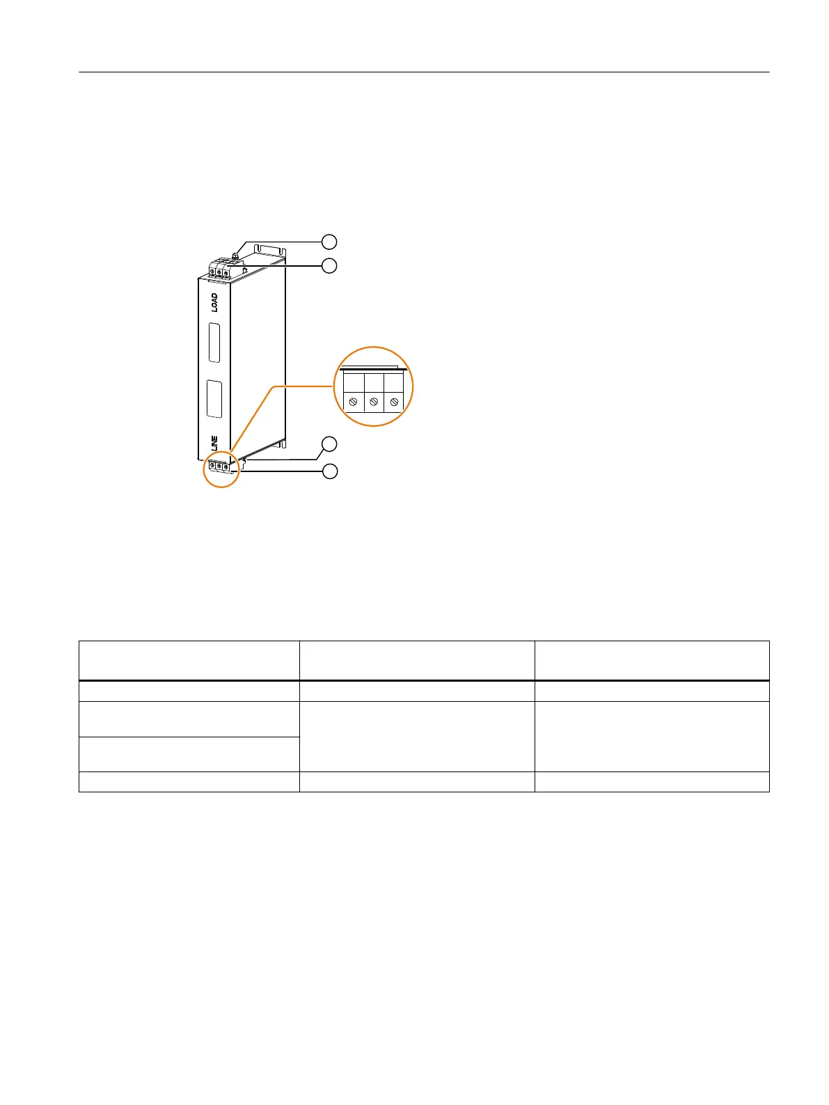
Overview diagram
① Protective conductor
② Load connection
③ Protective conductor
④ Line connection
Figure6-3 Interface overview line lters for Smart Line Modules
Table 6-3 Interface description line lters for Smart Line Modules
Article number
6SL5100-0HE21-6DD0 6SL5100-0HE22-4DD0
Rated power [kW] 16 24
Line connection
L1, L2, L3
Screw terminals 6 … 16mm
2
(AWG 10 ... AWG 6), 3-pole
2.0 … 2.2Nm (17.7 ... 19.5lbfin)
Screw terminals 6 …16mm
2
(AWG10 ... AWG 6), 3-pole
2.0 … 2.2Nm (17.7 ... 19.5lbfin)
Load connection
L1´, L2´, L3´
Protective conductor connection
1)
M8, 5.7 ... 6.3Nm (55.7lbfin) M8, 5.7 ... 6.3Nm (55.7lbfin)
1)
For ring cable lugs without insulation. The protective conductor may be connected using
either the upper screw or the lower screw. One of the screws remains unused. "Looping-
through" the protective connection to the line reactor is not permissible.
Line-side power components
6.5Line lter
Booksize power units
Equipment Manual, 09/2023, A5E53307519B AA 105
 Loading...


