Description
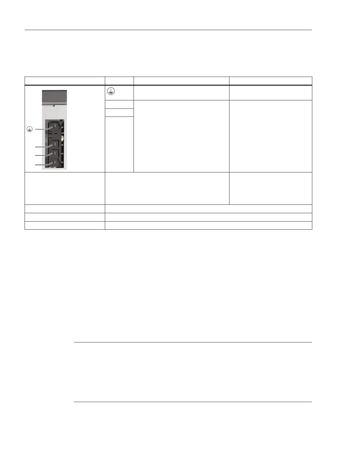
Table 7-2 X1: Line connection for 16kW and 24kW Smart Line Modules
X1: Line connection Terminal Function Technical data
Protective conductor connection at the
power plug
1.2 ... 1.5 Nm (10.6 lbf in)
W1 Line connection Supply voltage:
380…480V 3AC,
50/60(47...63) Hz
V1
U1
Connectable cable cross-sec‐
tions
Flexible
Flexible, with end sleeve without protective collar
Flexible, with end sleeve with protective collar
AWG / kcmil
6 … 16mm
2
6 … 16mm
2
6 … 16mm
2
10...6
Stripped length 12mm (0.47inch)
Screwdriver Slotted screwdriver 1.0x5.5mm
Tightening torque 1.2 ... 1.5 Nm (10.6 lbf in)
7.4.3 X21EP terminals/temperature sensor
Overview
A temperature sensor and the signal cable for the Enable Pulses (EP) function are connected at
the X21interface. The temperature sensor terminals are used to perform an external
temperature measurement.
The plug-in terminals are included in the Terminal Kit of the Smart Line Module.
Requirement
Note
Terminals X21.3and X21.4
Operation of the Line Module can only be enabled if the "1" signal is applied at the EP terminals.
If the "0" signal is applied at the EP terminals, pulse inhibit is enabled. As a consequence, energy
recovery is disabled and the bypass relays drop out. The DC link remains charged if the Line
Module is not isolated from the line supply in this process, for example because there is no main
contactor present.
Smart Line Modules
7.4Interfaces and connections
Booksize power units
118 Equipment Manual, 09/2023, A5E53307519B AA
 Loading...


