5. Remove length "b" of the insulation from the single cores according to the table above.
6. Use suitable ring or pipe-type cable lugs.
8.4.11.4 Connecting the motor connection cable and holding brake
Requirement
Required tools:
• Slotted screwdriver 0.8 x 5.5mm
• Socket wrench size10
Procedure
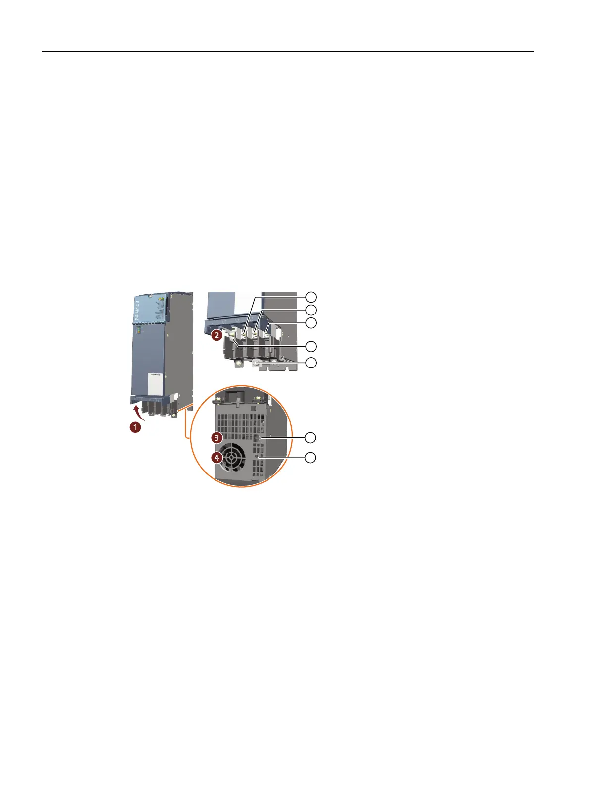
① U2
② V2
③ W2
④ Protective conductor connection for the motor
⑤ Protective conductor connection for the Motor Module
⑥ Interface X11 to connect the holding brake (BR+, BR-)
⑦ Threaded socket M4 for xing the shield connection clamp
Figure8-51 Connections for motor connection cable and holding brake at Motor Modules 45A and
60A
Connection X1 for the motor is implemented as motor connection block. The protective
conductor connection for the motor is also integrated in this. Proceed as follows to connect
the motor connection cable:
1. Open the locking of the cover of the motor connection block left and right and swing it
upwards. Slotted screwdriver 0.8 x 5.5mm
2. Remove the nuts from the threaded studs. Socket wrench size10
Motor Modules
8.4Motor Modules 45 A and 60 A
Booksize power units
206 Equipment Manual, 09/2023, A5E53307519B AA
 Loading...


