5.3 DC link busbars
5.3.1 Connecting the DC link busbars
Overview
Within the drive line-up, every component must be connected via the DC link busbars.
Alternatively, DC link adapters are used to individually supply a component. The connection is
explained in the following using a Smart Line Module and a Motor Module as example.
Requirement
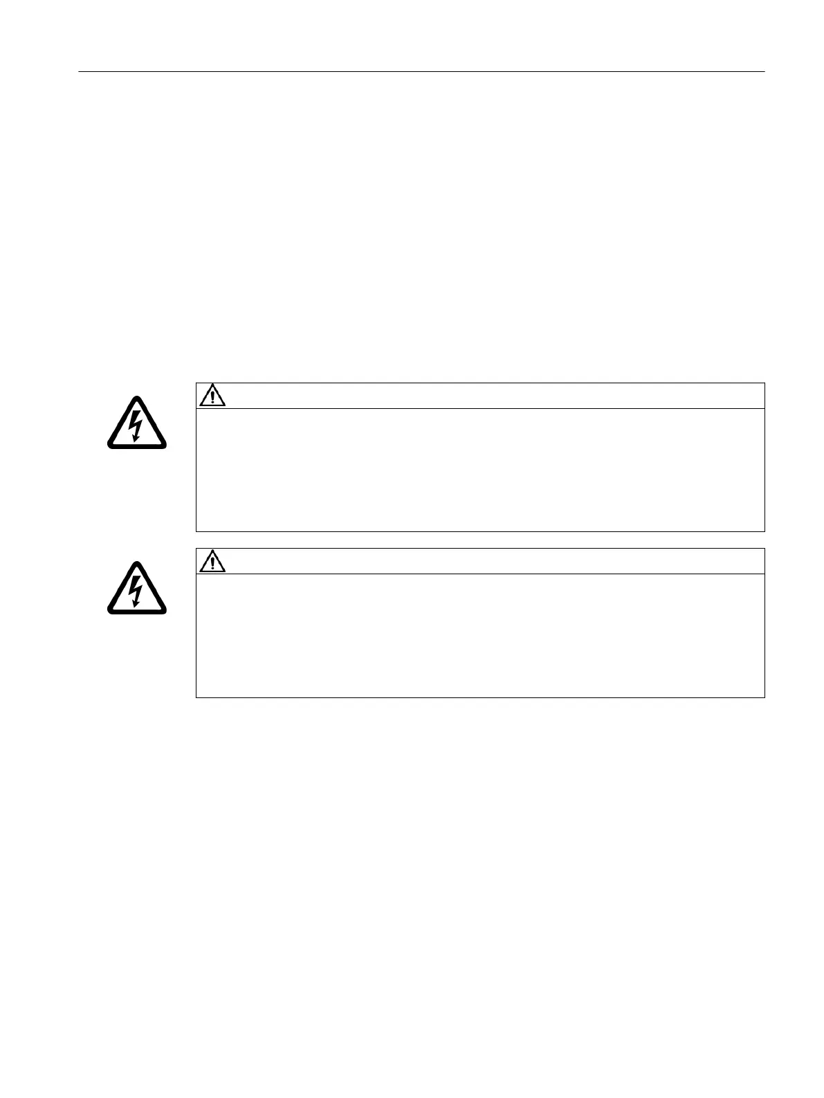
WARNING
Electric shock when the protective ap of the DC link is open
Live parts of the DC link are freely exposed when operating Motor Modules with open
protective ap. Contact with live parts can result in death or serious injury.
• Before opening the protective ap, bring the drive system into a no-voltage condition and
lock it out so that it cannot be switched on again.
• Check that the DC link is in a no voltage condition.
WARNING
Electric shock due to incorrectly installed DC link bridges
Incorrectly installed DC link bridges at the left-hand end of the drive line-up can cause an
electric shock.
• For all 50mm wide modules, remove the DC link bridge.
• For all components that are wider, you must neither move the DC link bridge to the left nor
remove it, as the DC link bridge ensures the mechanical stability of the DC link busbars.
In a drive line-up, the components are mounted next to one another.
Required tools:
• Slotted screwdriver 1.0x5.5mm to release the protective ap
• Torx screwdriver TX20 for the DC link screws
Mounting
5.3DC link busbars
Booksize power units
Equipment Manual, 09/2023, A5E53307519B AA 87
 Loading...


