Only use the temperature sensor input of the Motor Module if the following conditions are
fullled:
• The connected motors are not equipped with an integrated DRIVE-CLiQ interface.
• The temperature values are not acquired via another component (Sensor Module Cabinet,
Sensor Module External, Terminal Module).
Description
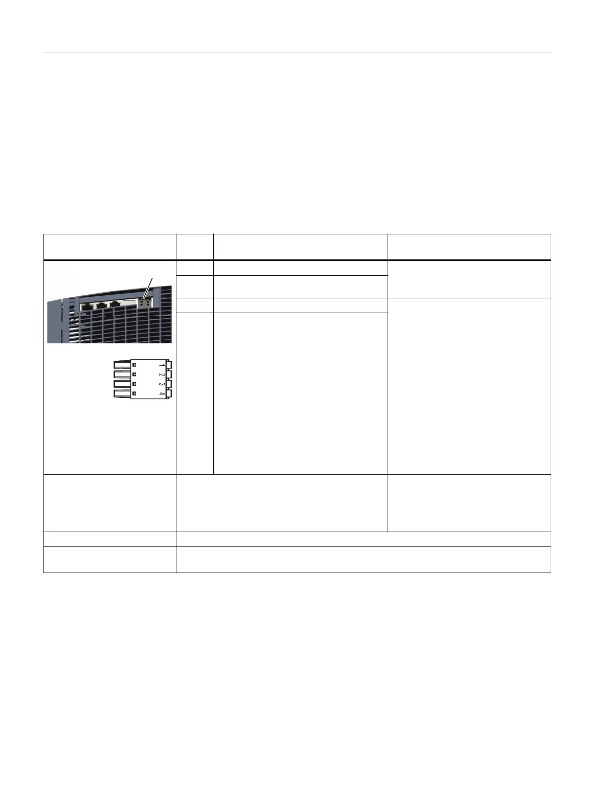
Table 8-3 X21/X22: EP terminal/temperature sensor for Motor Modules 3 ... 200A
X21/X22: EP terminals / tem‐
perature sensor
Termi‐
nal
Designation Technical data
1 + Temp Temperature sensors
1)
: Pt1000 / PTC /
KTY84-130 / bimetallic switch with NC
contact
2 - Temp
3 EP + (Enable Pulses +) Voltage: -3…+30VDC
Electrical isolation: Yes
Input characteristic acc. to
IEC61131-2, type1 and type3
Input voltage (including ripple)
"1" signal: 11…30V
signal "0": -3…+5V
Input current
at 24VDC: 2.5...4mA
at < 1.5 mA: "0" signal reliably detected
Input delay
for "0" → "1": typ.25μs / max.50μs
for "1" → "0": typ.110μs+2μs/m /
max.150μs+4μs/m
4 EP M (Enable Pulses M)
Connectable cable cross-sec‐
tions
Rigid, exible
Flexible, with end sleeve without protective collar
Flexible, with end sleeve with protective collar
AWG / kcmil
0.25...1.5 mm
2
0.25...1.5mm
2 1)
0.25...0.75 mm
2
24…16
Stripped length 8mm (0.31inch)
Screwdriver to release the
terminal
Slotted screwdriver 0.4 x 2.5mm
1)
Accuracy of temperature measurement (temperature sensor, including evaluation):
- Pt1000: ±5°C (Pt1000 tolerance ClassB acc. to EN60751)
- PTC: ±5°C
- KTY: ±7°C
8.3.1.4 X1 - X2 motor and holding brake connection
Overview
The motor and the holding brake are connected to a connection plug (power connector) via the
motor cable. The connection plug is not included in the scope of delivery.
Motor Modules
8.3Motor Modules 3 ... 30 A and 2x3 ... 2x18 A
Booksize power units
156 Equipment Manual, 09/2023, A5E53307519B AA
 Loading...


