Description
Line reactors are interfaces on the line side for the Smart Line Modules. They limit line harmonics
to permissible values. For this reason, line reactors must always be used when operating the Line
Modules.
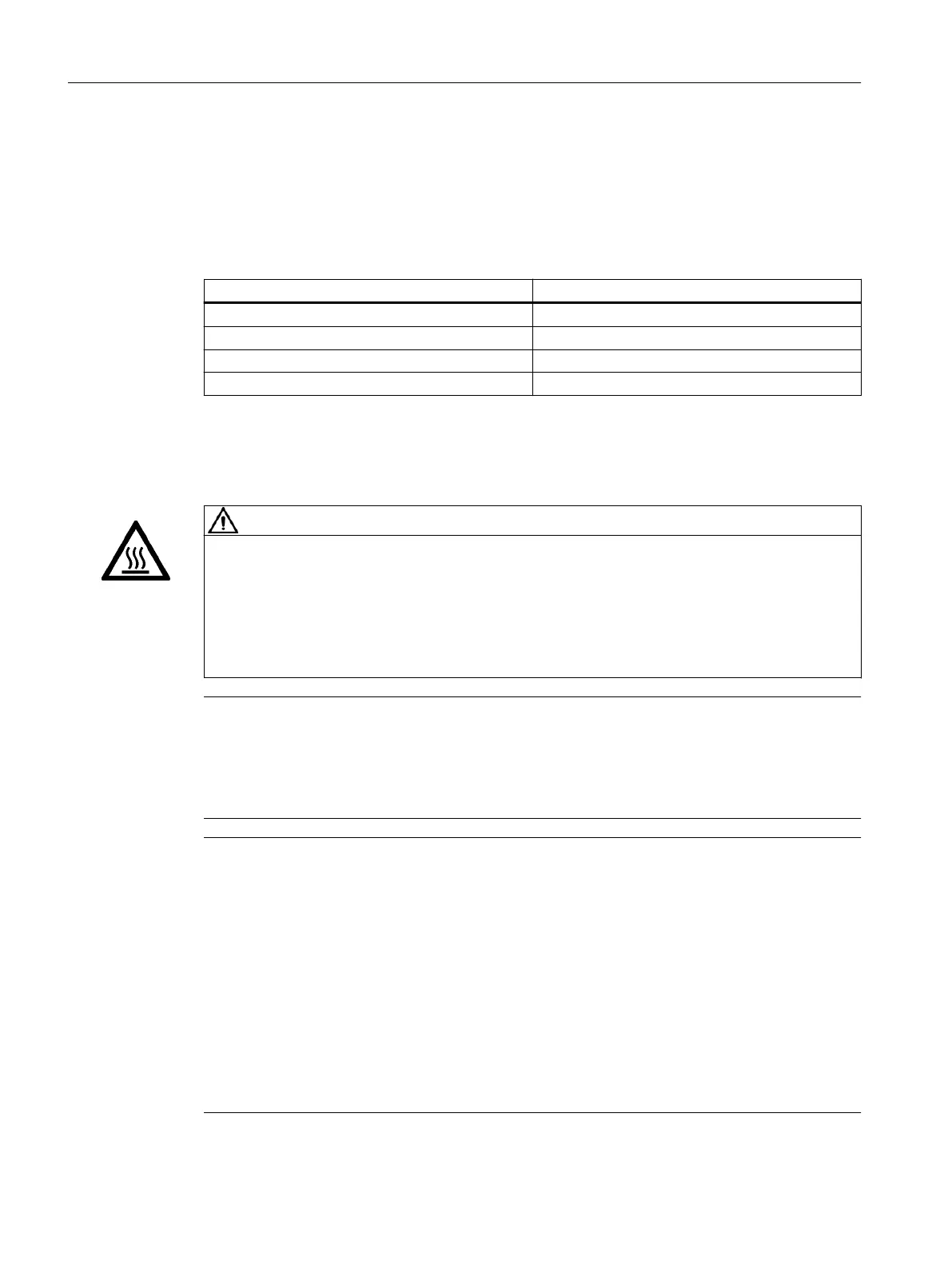
Table 6-5 Line reactors for Smart Line Modules
Line reactors Article number
16kW C type 6SL3100-0EE21-6AA0
16kW D type 6SL5100-0EE21-6AD0
24kW C type 6SL5100-0EE22-4AC0
24kW D type 6SL5100-0EE22-4AD0
6.6.2 Safety information
CAUTION
Burns resulting from high surface temperature of the line reactor
The line reactors can become very hot. You can get seriously burnt when touching the surface.
• Mount the line reactors so that contact is not possible. If this is not possible, attach clearly
visible and understandable warning notices at hazardous positions.
• To prevent adjacent components from suering damage due to these high temperatures,
maintain a ventilation clearance of 100mm on all sides of the line reactors.
Note
Malfunctions through magnetic elds
Line reactors produce magnetic elds that can disturb or damage components and cables.
• Arrange the components and cables at a suitable distance (at least 200mm) or shield the
magnetic elds appropriately.
Note
Length of connecting cables
The connecting cables between line reactor and Line Module, as well as between line reactor
and line lter, must be kept as short as possible (max.10m).
Use shielded connecting cables and connect the cable shields at both ends.
Shielding is not required if the following preconditions are satised:
• The cables do not exceed 1m in length.
• The cables are laid ush with the rear metal panel of the control cabinet.
• The cables are laid in a way that keeps them physically separate from signal cables.
All signal cables must be laid separately from the line reactor and from unshielded connecting
cables of the reactor with a minimum clearance of 200mm.
Line-side power components
6.6Line reactors
Booksize power units
108 Equipment Manual, 09/2023, A5E53307519B AA
 Loading...


