5.2.4.2 Single-tier conguration with center infeed
Overview diagram
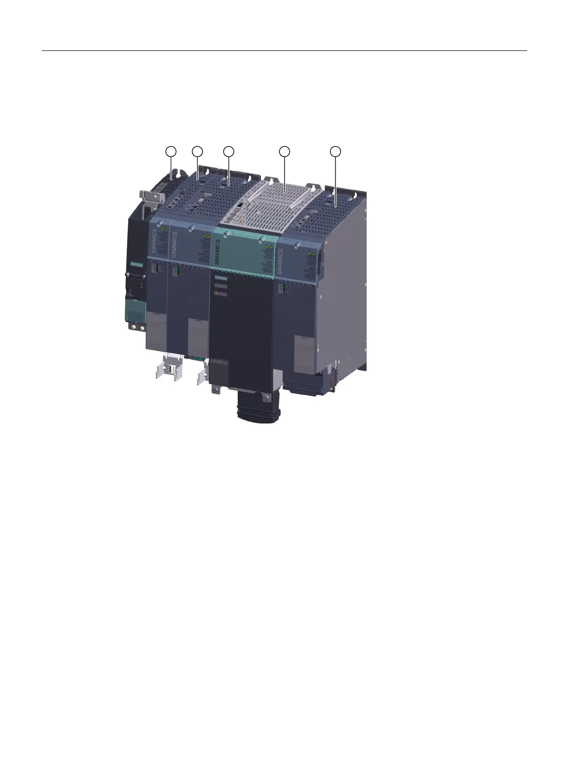
① SINAMICS S120 Control Unit 320-2
② SINAMICS S220 Motor Module 2x9A
③ SINAMICS S220 Motor Module 30A
④ SINAMICS S120 Active Line Module
⑤ SINAMICS S220 Motor Module 60A
Figure5-4 Example of a single-tier drive line-up with center infeed
The center infeed represents the ideal solution if the continuous current-carrying capacity of
the DC link busbars is exceeded for a typical conguration to the right.
The inverse sequence applies when the infeed is located to the right of the drive line-up. The
following components are arranged from right to left at the Line Module:
• Motor Modules depending on their power, starting with the highest power
• DC link components, such as Braking Modules, at the end of the tier
Mounting
5.2Layout of the components
Booksize power units
84 Equipment Manual, 09/2023, A5E53307519B AA
 Loading...


