5SBOTGPSNFSPS
HFOFSBUPS
5PUIFTZTUFN
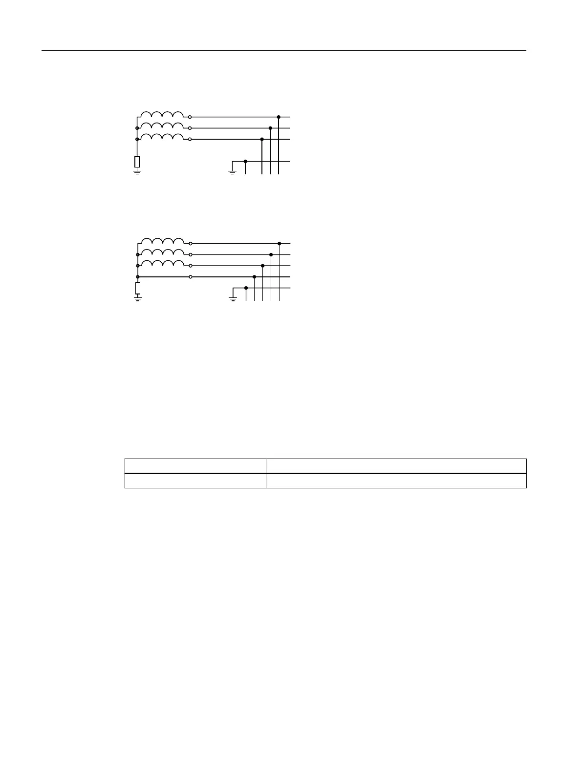
&YBNQMF*5OFUXPSLXJUIPVUOFVUSBMDPOEVDUPS
&YBNQMF*5OFUXPSLXJUIOFVUSBMDPOEVDUPS
5SBOTGPSNFSPS
HFOFSBUPS
5PUIFTZTUFN
-
-
-
1&
-
-
-
/
1&
Figure4-3 IT system
4.8 Conditions for the line connection
Description
Table 4-3 Conditions for connecting Smart Line Modules to the line supply
Component Description
1)
Smart Line Module Operation on line supplies from S
K line
/P
rated
≥ 30
1)
S
K line
= short-circuit power of the line supply; P
rated
= rated power of the Line Module
4.9 Power failure-buering concept
Description
The system comprising Line Modules and Motor Modules must be dimensioned so that at the
rated power there is no functional restriction (3ms of the line supply dip or interruption
according to IEC 61800-3 (2017)).
General statements cannot be made regarding the buer times. These can be extended
a multiple number of times depending on the particular drive system and the operating
conditions. Signicantly longer buer times can be obtained when components operate in
either the motoring or generating mode. The existing installation must be assessed on a
case-for-case basis.
Application planning
4.9Power failure-buering concept
Booksize power units
46 Equipment Manual, 09/2023, A5E53307519B AA
 Loading...


