8.3.1.2 Interfaces (lower side)
Overview diagram
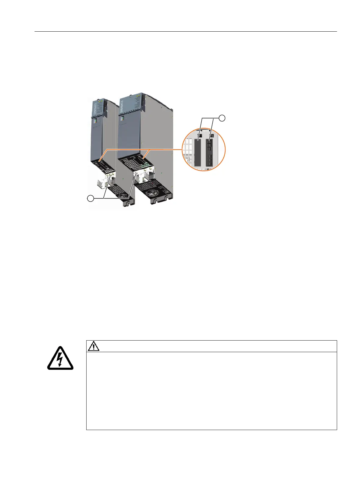
① Screw for the protective conductor connection of the Motor Module
② X1 - X2: Motor connection with holding brake and protective conductor connection to the motor
Figure8-4 Interface overview of Motor Modules 3 ... 30 A, 2x3 ... 2x18 A (lower side)
8.3.1.3 X21/X22EP terminals / temperature sensor
Overview
A temperature sensor and the signal cable for the enable pulses (=EP) function are connected at
interface X21 for Single Motor Modules or X21/X22 for Double Motor Modules.
The plug-in terminals are included in the Terminal Kit of the Motor Module.
Requirement
WARNING
Electric shock when the motor temperature sensor insulation fails
When connecting temperature sensors which are not isolated from the motor power circuit
according to safe electrical separation, arcing to the signal electronics may occur.
• Use motors whose temperature sensors have safe electrical separation.
• Use only connecting cables and connectors with safe electrical separation between the
cores of the temperature sensor and the cores of the power circuit.
• If safe electrical separation cannot be guaranteed (for linear motors or third-party motors,
for example), use a Sensor Module External (SME120 or SME125) or Terminal Module
TM120.
Motor Modules
8.3Motor Modules 3 ... 30 A and 2x3 ... 2x18 A
Booksize power units
Equipment Manual, 09/2023, A5E53307519B AA 155
 Loading...


