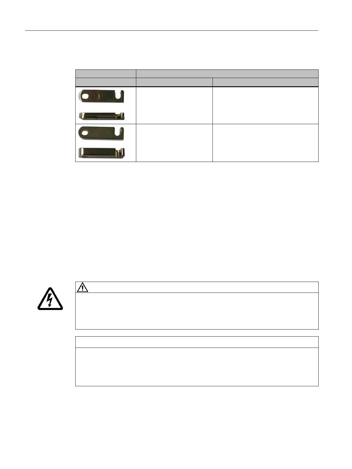
5.3.2 Order data DC link bridge
Accessories Article number Description
included in the scope of deliv‐
ery
4mm bridge
6SL3162-2BB00-0AA0
Included in the scope of deliv‐
ery for components wider than
100 mm
6mm bridge to achieve a continuous cur‐
rent-carrying capacity of 200A
5.4 24V terminal adapter
5.4.1 Mounting the 24V terminal adapter
Overview
The 24V terminal adapter is included in the Terminal Kit of the Smart Line Module.
Requirement
WARNING
Electric shock if the cutout in the protective ap has been broken out
Live parts are exposed if the 24 V terminal adapter is again removed at a later point in time.
Touching live components can result in death or severe injury.
• Replace the protective ap with the broken out cutouts with a new protective ap.
NOTICE
Damage to the 24V terminal adapter as a result of incorrect mounting/removal
Incorrect insertion/withdrawal of the 24V terminal adapter can damage it.
• Only remove the 24 V terminal adapter vertically in relation to the front plate.
• Inserting and withdrawing the 24 V terminal adapter a maximum of 5 times.
Mount the 24 V terminal adapter on the left side of the component that is located to the far
left to avoid space problems with the 24 V connectors.
Mounting
5.424V terminal adapter
Booksize power units
90 Equipment Manual, 09/2023, A5E53307519B AA
 Loading...


