4.13.2 Calculating the power loss for Motor Modules in typical applications
Overview
The information on the power losses in the previous chapters are maximum values, which occur
in the most unfavorable case. For typical applications, the losses are lower.
The following applies as typical application:
• Maximum motor cable length, 30m
• 4kHz pulse frequency
• DC link voltage 540V - 600V
Description
Power losses for typical applications can be calculated based on the following formula:
P
V
[W] =a+S
1
•(I
1
+I
2
)+S
2
•(I
1
2
+I
2
2
)
a Electronics losses of the Motor Module
S
1
, S
2
Coecients to calculate power loss
I
1
Current (arithmetic mean value) of the 1st axis
I
2
Current (arithmetic mean value) of the 2nd axis
Overview of required coecients
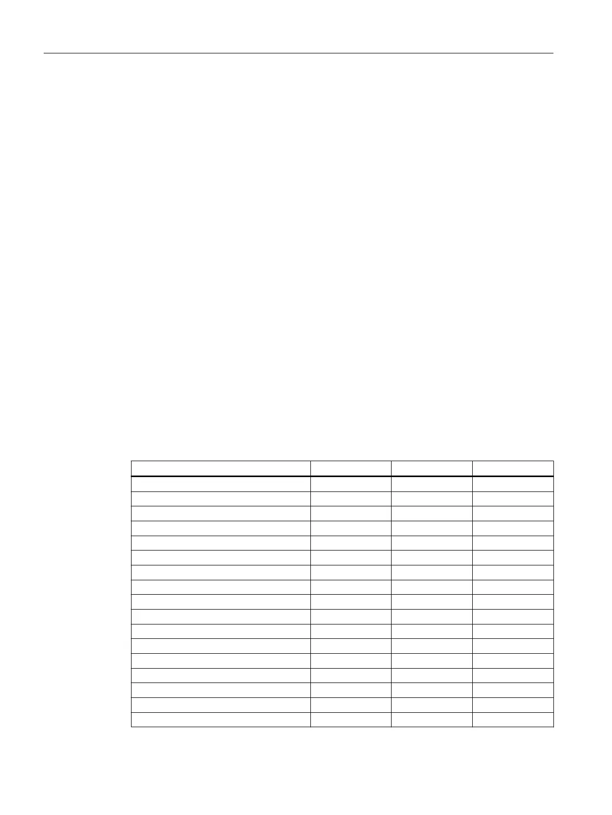
Table 4-17 Coecients to calculate the power loss in the control cabinet for Motor Modules for
typical applications
Motor Module a [W] S
1
[W/A] S
2
[W/A
2
]
Single Motor Module 3A 17 3.29 0.205
Single Motor Module 5A 18 3.29 0.205
Single Motor Module 9A 19 3.29 0.205
Single Motor Module 18A 24 3.29 0.205
Single Motor Module 24A 24 3.50 0.140
Single Motor Module 30A 18 4.71 0.113
Single Motor Module 30A (slim) 29 4.71 0.113
Single Motor Module 45A 24 4.40 0.060
Single Motor Module 60A 24 4.40 0.055
Single Motor Module 85A 125 6.01 0.017
Single Motor Module 132A 125 6.01 0.017
Single Motor Module 200A 125 6.01 0.017
Double Motor Module 2x3A 24 5.20 0.200
Double Motor Module 2x5A 26 5.20 0.200
Double Motor Module 2x9A 26 5.18 0.247
Double Motor Module 2x18A 23 5.57 0.091
Double Motor Module 2x18A (slim) 31 5.57 0.091
Application planning
4.13Power losses
Booksize power units
62 Equipment Manual, 09/2023, A5E53307519B AA
 Loading...


