Description
Table 7-4 X24: 24V terminal adapter for 16kW and 24kW Smart Line Modules
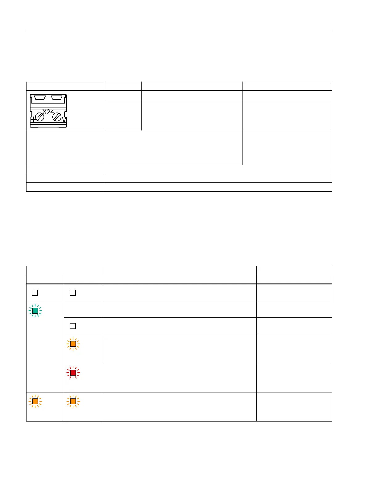
X24: 24V terminal adapter Pin/terminal Pin assignment/designation Technical data
+ 24V power supply 24V DC supply voltage
M Ground Electronics ground
Connectable cable cross-sec‐
tions
Flexible
Flexible, with end sleeve without protective collar
Flexible, with end sleeve with protective collar
AWG / kcmil
0.5 … 6mm
2
0.5 … 6mm
2
0.5 … 6mm
2
20...8
Stripped length 12mm (0.47inch)
Screwdriver Slotted screwdriver 1.0 x 4.0mm
Tightening torque 1.2… 1.5Nm (10.6...13.3lbfin)
7.5 LED description
Response of the LEDs in operation
Table 7-5 Meaning of the LEDs on the Smart Line Module
LEDs Description, cause Remedy
RDY1 DC LINK
The electronics power supply is missing or outside the permis‐
sible tolerance range.
Check the 24 V supply.
Green
–
1)
The component is ready for operation. Cyclic DRIVE-CLiQ com‐
munication is taking place.
–
The DC link voltage is <50V. –
Orange
The DC link voltage is present. –
Red
The DC link voltage lies above the permissible tolerance range. Check the line voltage.
Orange Orange
DRIVE-CLiQ communication is being established. –
Smart Line Modules
7.5LED description
Booksize power units
120 Equipment Manual, 09/2023, A5E53307519B AA
 Loading...


