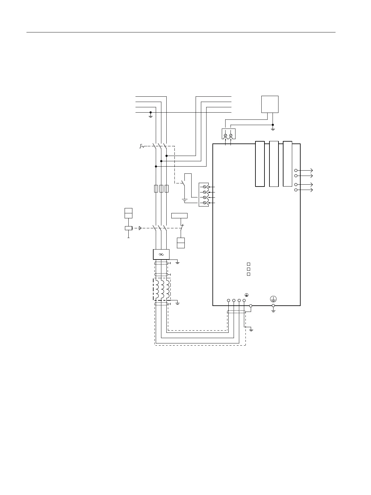
7.6 Connection example
Connection example
Main switch
Line contactor
(optional)
Fuses
Line filter
Line reactor
DRIVE-CLiQ socket 0
DRIVE-CLiQ socket 2
DRIVE-CLiQ socket 1
ext.
24 V
+Temp
-Temp
5)
5)
5)
3)4)
DC 24 V
CU
DI
X24
M
+
M+
2)
2)
CU
DO
W1V1U1
EP M
1
2
3
4
X21
EP +24 V
1)
PE
1L1
1L2
1L3
PE
L1
L2
L3
X200
LEDs
DC LINK
RDY 1
DCP
DCN
+
M
X201 X202
Smart Line
Module
;
1) Leading normally closed (NC) contact t>10ms
The leading NC contact is not required when using a VSM10 Voltage Sensing Module.
2) DI/DO (= digital input/digital output), controlled by the Control Unit
3) No additional load permitted downstream of the line contactor
4) Observe the current-carrying capacity of the digital output. It may be necessary to use an output
coupling link.
5) Contact is established through the rear panel or shield rails in accordance with the EMC installa‐
tion guideline
Figure7-3 Connection example for 16kW and 24 kW Smart Line Modules
Smart Line Modules
7.6Connection example
Booksize power units
122 Equipment Manual, 09/2023, A5E53307519B AA
 Loading...


