Description
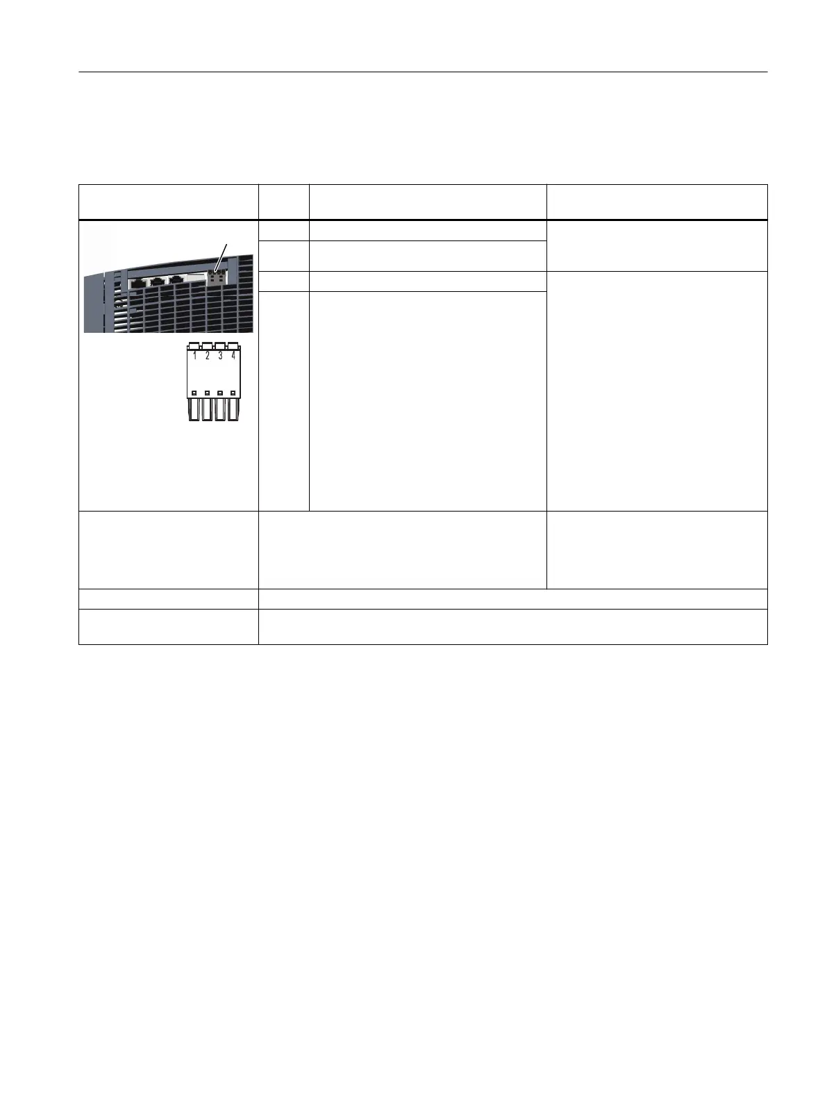
Table 7-3 X21: EP terminal/temperature sensor for 16kW and 24kW Smart Line Modules
X21: EP terminals / tempera‐
ture sensor
Termi‐
nal
Designation Technical data
1 + Temp Temperature sensors
1)
: Pt1000/PTC/
KTY84-130/bimetallic switch with NC
contact
2 - Temp
3 EP + (Enable Pulses +) Voltage: -3…+30VDC
Electrical isolation: Yes
Input characteristic acc. to
IEC61131-2, type1 and type3
Input voltage (including ripple)
"1" signal: 11…30V
signal "0": -3…+5V
Input current
at 24VDC: 2.5...4mA
at < 1.5 mA: "0" signal reliably detected
Input delay
for "0" → "1": typ.25μs / max.50μs
for "1" → "0": typ.110μs+2μs/m /
max.150μs+4μs/m
4 EP M (Enable Pulses M)
Connectable cable cross-sec‐
tions
Rigid, exible
Flexible, with end sleeve without protective collar
Flexible, with end sleeve with protective collar
AWG / kcmil
0.25...1.5 mm
2
0.25...1.5 mm
2
0.25...0.75 mm
2
24…16
Stripped length 8mm (0.31inch)
Screwdriver to release the
terminals
Slotted screwdriver 0.4 x 2.5mm
1)
Accuracy of temperature measurement (temperature sensor, including evaluation):
- Pt1000: ±5°C (Pt1000 tolerance ClassB acc. to EN60751)
- PTC: ±5°C
- KTY: ±7°C
Temperatures are detected but not evaluated in the Smart Line Module.
7.4.4 X24 24V terminal adapter
Overview
The 24V terminal adapter is connected at the X24interface.
Smart Line Modules
7.4Interfaces and connections
Booksize power units
Equipment Manual, 09/2023, A5E53307519B AA 119
 Loading...


